100%
AT-98
A340E (2JZ-GTE) AUTOMATIC TRANSMISSION - COMPONENT PARTS INSTALLATION
AT5232
Flange
D
P
D
P
D
P
D
P
D
Flange (4.0 mm)
AT5401
AT5233
SST
AT5282
AT5147
21. CHECK OUTPUT SHAFT
(a) Using a dial indicator, measure the end play of the output shaft.
End play:
1.63-2.89 mm (0.0642-0.1138 in.)
If the values are non-standard, check for improper installation.
(b) Check to see that output shaft rotates smoothly.
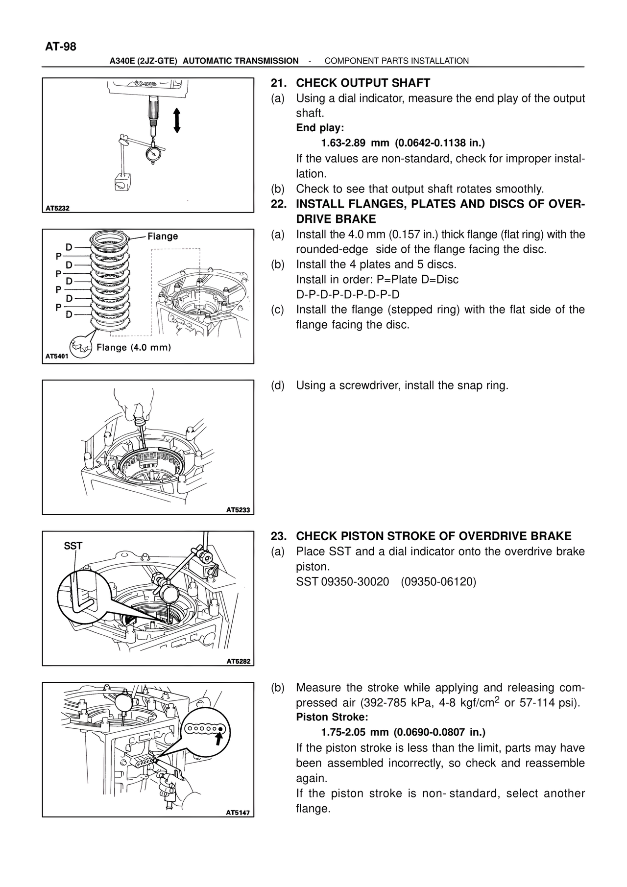
22. INSTALL FLANGES, PLATES AND DISCS OF OVERDRIVE BRAKE
(a) Install the 4.0 mm (0.157 in.) thick flange (flat ring) with the rounded-edge side of the flange facing the disc.
(b) Install the 4 plates and 5 discs.
Install in order: P=Plate D=Disc
D-P-D-P-D-P-D-P-D
(c) Install the flange (stepped ring) with the flat side of the flange facing the disc.
(d) Using a screwdriver, install the snap ring.
23. CHECK PISTON STROKE OF OVERDRIVE BRAKE
(a) Place SST and a dial indicator onto the overdrive brake piston.
SST 09350-30020 (09350-06120)
(b) Measure the stroke while applying and releasing compressed air (392-785 kPa, 4-8 kgf/cm2 or 57-114 psi).
Piston Stroke:
1.75-2.05 mm (0.0690-0.0807 in.)
If the piston stroke is less than the limit, parts may have been assembled incorrectly, so check and reassemble again.
If the piston stroke is non-standard, select another flange.