100%
AT-9
A340E(Others) AUTOMATIC TRANSMISSION - OPERATION
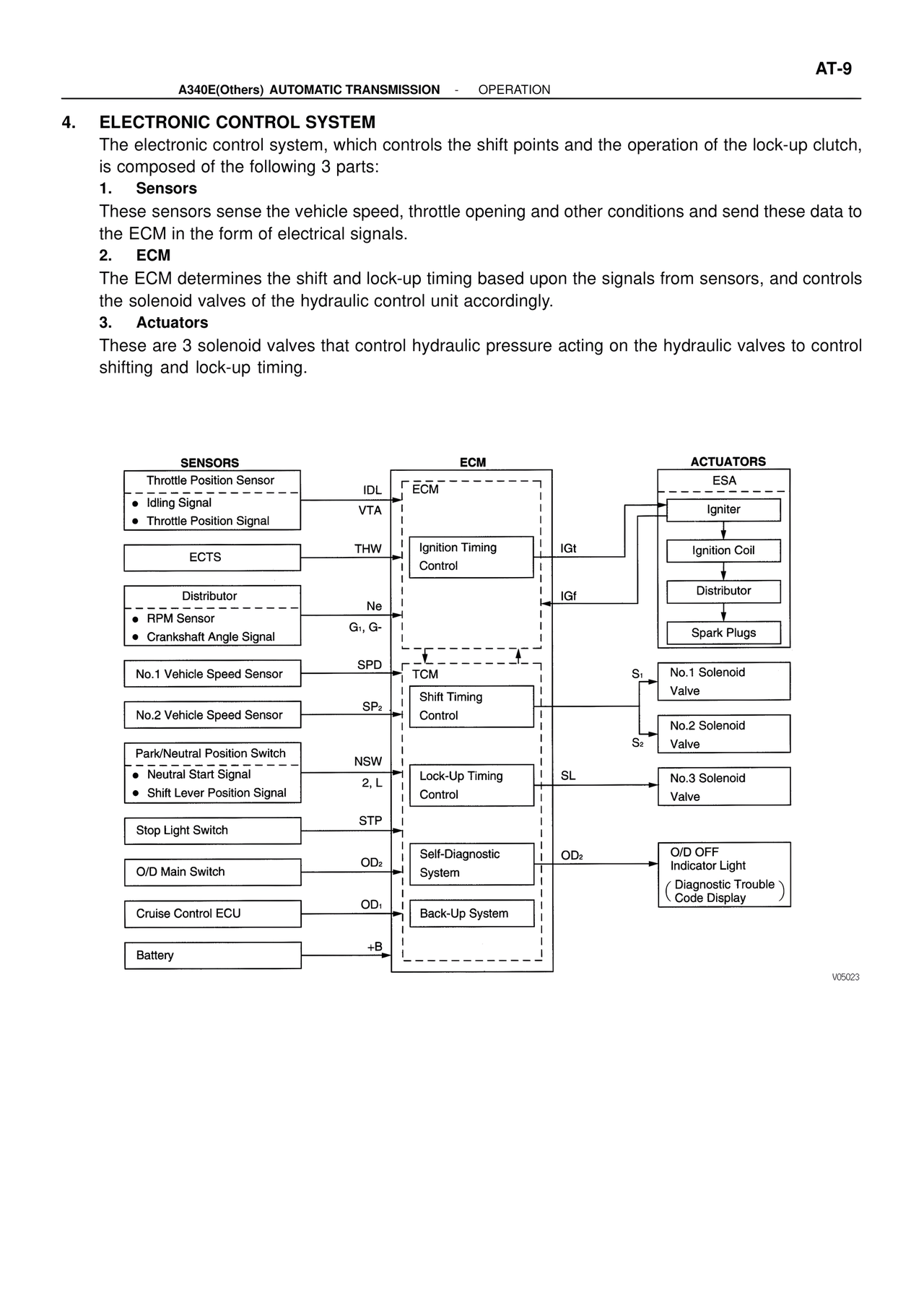
4. ELECTRONIC CONTROL SYSTEM
The electronic control system, which controls the shift points and the operation of the lock-up clutch,
is composed of the following 3 parts:
1. Sensors
These sensors sense the vehicle speed, throttle opening and other conditions and send these data to
the ECM in the form of electrical signals.
2. ECM
The ECM determines the shift and lock-up timing based upon the signals from sensors, and controls
the solenoid valves of the hydraulic control unit accordingly.
3. Actuators
These are 3 solenoid valves that control hydraulic pressure acting on the hydraulic valves to control
shifting and lock-up timing.
SENSORS ECM ACTUATORS
Throttle Position Sensor ESA
• Idling Signal IDL ECM
• Throttle Position Signal VTA Igniter
ECTS THW Ignition Timing IGt Ignition Coil
Control
Distributor IGf Distributor
• RPM Sensor Ne
• Crankshaft Angle Signal G1, G- Spark Plugs
No.1 Vehicle Speed Sensor SPD TCM S1 No.1 Solenoid
Shift Timing Valve
No.2 Vehicle Speed Sensor SP2 Control S2 No.2 Solenoid
Valve
Park/Neutral Position Switch NSW
• Neutral Start Signal Lock-Up Timing SL No.3 Solenoid
• Shift Lever Position Signal 2, L Control Valve
Stop Light Switch STP
Self-Diagnostic OD2 O/D OFF
O/D Main Switch OD2 System Indicator Light
( Diagnostic Trouble
Cruise Control ECU OD1 Back-Up System Code Display )
Battery +B
V05023