100%
AT-1 16
A340E(Others) AUTOMATIC TRANSMISSION - COMPONENT PARTS INSTALLATION
AT8481
Z06796
19. CHECK OUTPUT SHAFT
(a) Using a dial indicator, measure the end play of the output
shaft with hand.
End play:
0.27 - 0.86 mm (0.0106 - 0.0339 in.)
If the values are non-standard, check for an improper
installation.
(b) Check to see that output shaft rotates smoothly.
Flange
D
P
D
P
D
P
D
P
D
Flange (4.0 mm)
Q00637
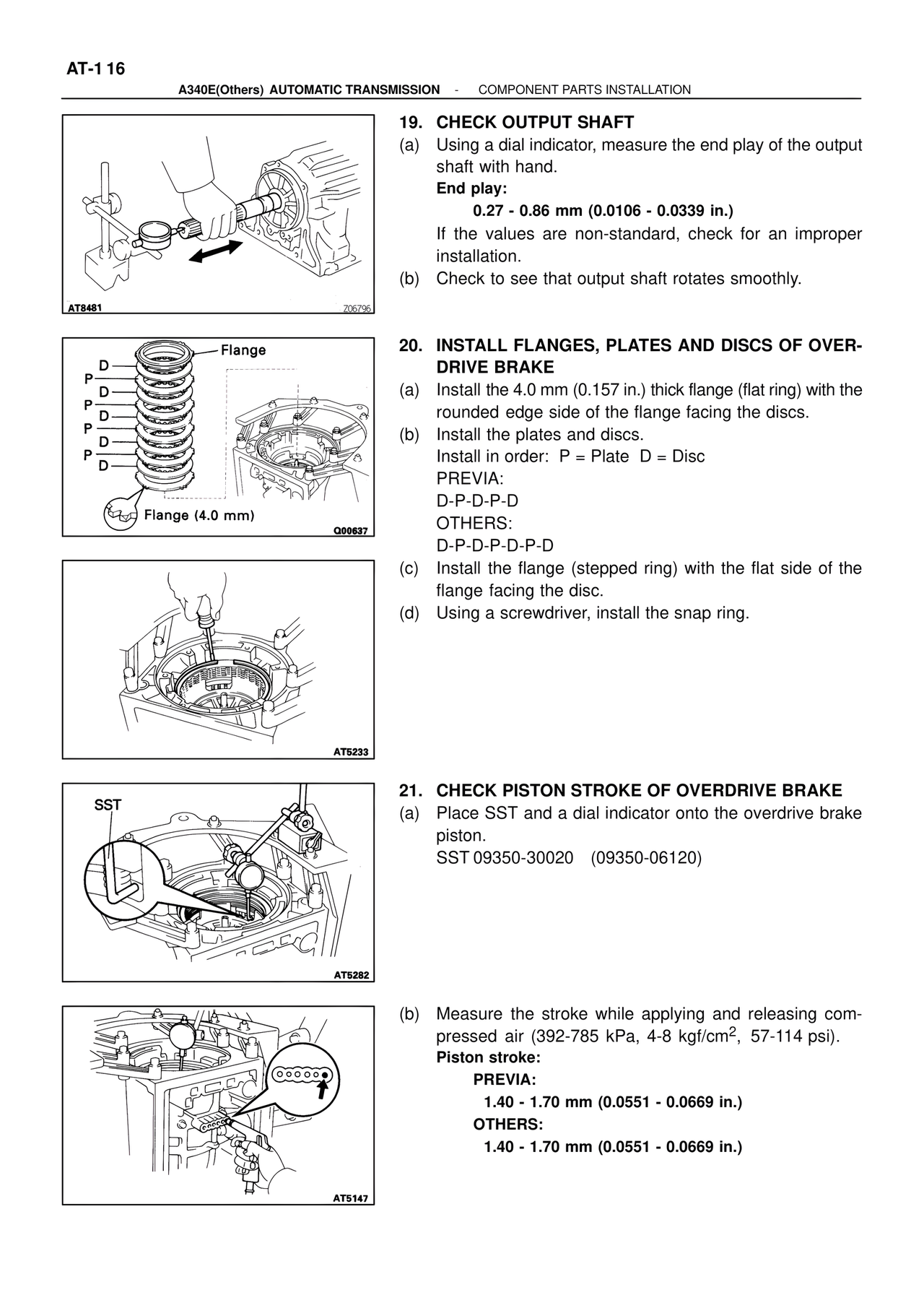
20. INSTALL FLANGES, PLATES AND DISCS OF OVER-
DRIVE BRAKE
(a) Install the 4.0 mm (0.157 in.) thick flange (flat ring) with the
rounded edge side of the flange facing the discs.
(b) Install the plates and discs.
Install in order: P = Plate D = Disc
PREVIA:
D-P-D-P-D
OTHERS:
D-P-D-P-D-P-D
(c) Install the flange (stepped ring) with the flat side of the
flange facing the disc.
(d) Using a screwdriver, install the snap ring.
AT5233
SST
AT5282
21. CHECK PISTON STROKE OF OVERDRIVE BRAKE
(a) Place SST and a dial indicator onto the overdrive brake
piston.
SST 09350-30020 (09350-06120)
AT5147
(b) Measure the stroke while applying and releasing com-
pressed air (392-785 kPa, 4-8 kgf/cm2, 57-114 psi).
Piston stroke:
PREVIA:
1.40 - 1.70 mm (0.0551 - 0.0669 in.)
OTHERS:
1.40 - 1.70 mm (0.0551 - 0.0669 in.)