← p.015p.017 →
ATTE/A340 Automatic Trans (GTE) — NO.1 Vehicle Speed Sensor Assembly Replacement, page 16
16 / 118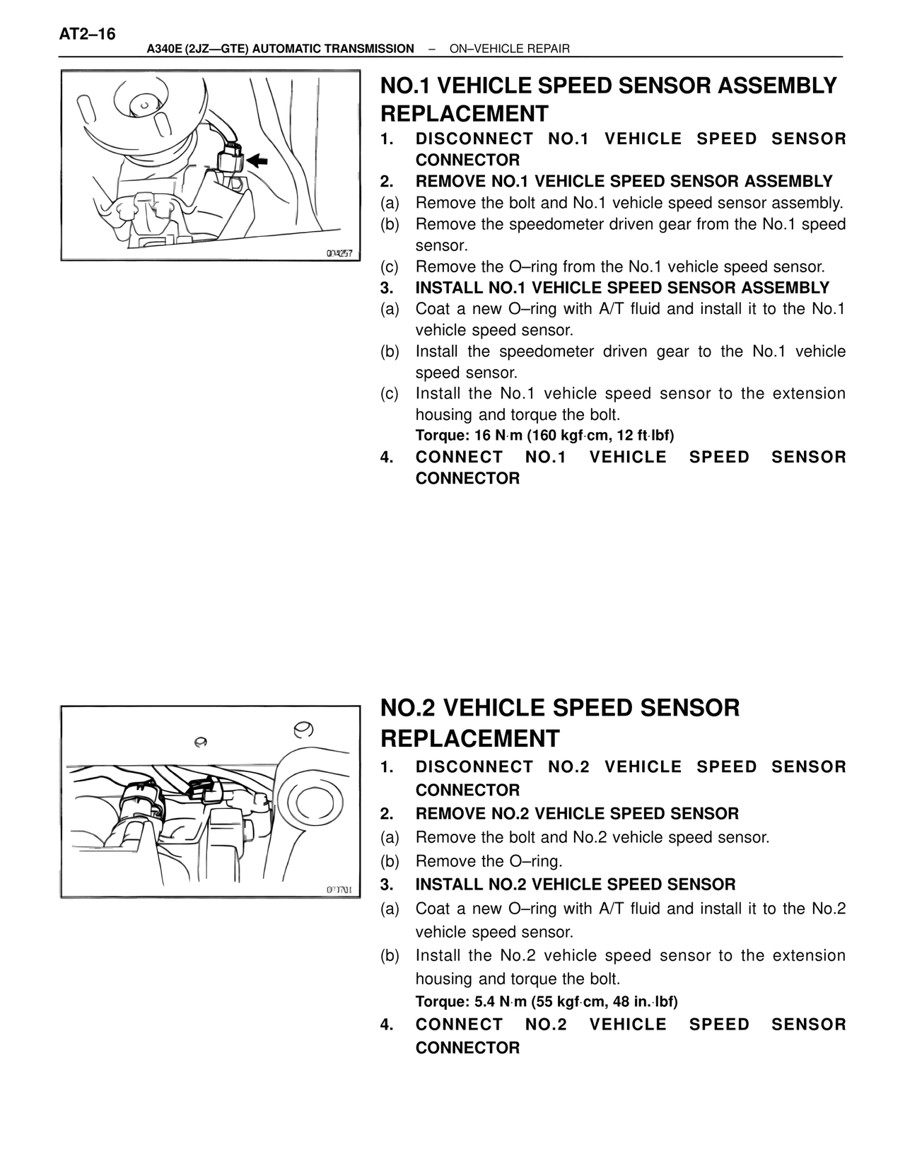
100%
Page text (OCR transcript)
AT2–16
A340E (2JZ—GTE) AUTOMATIC TRANSMISSION  –  ON–VEHICLE REPAIR

NO.1 VEHICLE SPEED SENSOR ASSEMBLY REPLACEMENT
1. DISCONNECT NO.1 VEHICLE SPEED SENSOR CONNECTOR
2. REMOVE NO.1 VEHICLE SPEED SENSOR ASSEMBLY
(a) Remove the bolt and No.1 vehicle speed sensor assembly.
(b) Remove the speedometer driven gear from the No.1 speed sensor.
(c) Remove the O–ring from the No.1 vehicle speed sensor.
3. INSTALL NO.1 VEHICLE SPEED SENSOR ASSEMBLY
(a) Coat a new O–ring with A/T fluid and install it to the No.1 vehicle speed sensor.
(b) Install the speedometer driven gear to the No.1 vehicle speed sensor.
(c) Install the No.1 vehicle speed sensor to the extension housing and torque the bolt.
Torque: 16 N·m (160 kgf·cm, 12 ft·lbf)
4. CONNECT NO.1 VEHICLE SPEED SENSOR CONNECTOR

004257

NO.2 VEHICLE SPEED SENSOR REPLACEMENT
1. DISCONNECT NO.2 VEHICLE SPEED SENSOR CONNECTOR
2. REMOVE NO.2 VEHICLE SPEED SENSOR
(a) Remove the bolt and No.2 vehicle speed sensor.
(b) Remove the O–ring.
3. INSTALL NO.2 VEHICLE SPEED SENSOR
(a) Coat a new O–ring with A/T fluid and install it to the No.2 vehicle speed sensor.
(b) Install the No.2 vehicle speed sensor to the extension housing and torque the bolt.
Torque: 5.4 N·m (55 kgf·cm, 48 in.·lbf)
4. CONNECT NO.2 VEHICLE SPEED SENSOR CONNECTOR

0°1701