← p.014p.016 →
BE/Body Electrical Systems — Combination Switch Disassembly and Assembly, page 15
15 / 203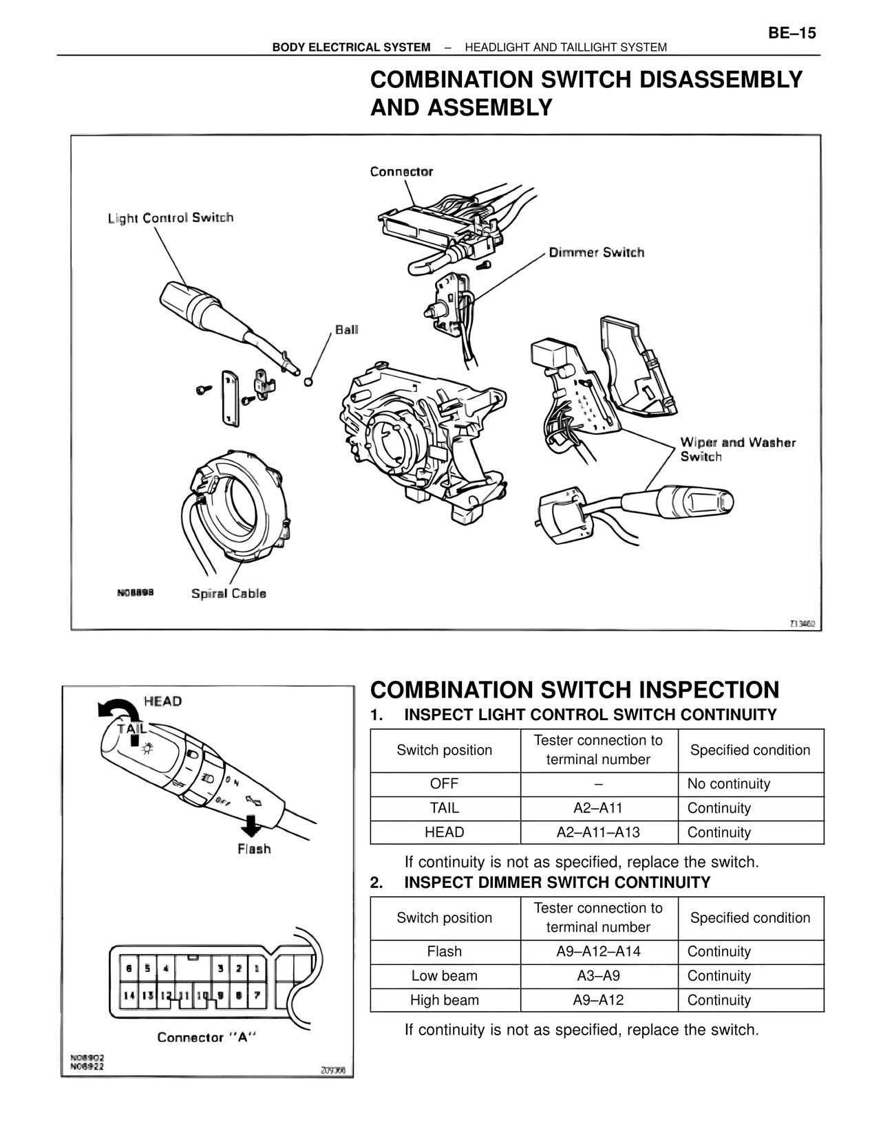
100%
Page text (OCR transcript)
BODY ELECTRICAL SYSTEM – HEADLIGHT AND TAILLIGHT SYSTEM

BE–15

COMBINATION SWITCH DISASSEMBLY
AND ASSEMBLY

Connector
Light Control Switch
Dimmer Switch
Ball
Wiper and Washer
Switch
N08898
Spiral Cable
Z13462

COMBINATION SWITCH INSPECTION

HEAD
TAIL
Flash

1. INSPECT LIGHT CONTROL SWITCH CONTINUITY

Switch position | Tester connection to terminal number | Specified condition
OFF | – | No continuity
TAIL | A2–A11 | Continuity
HEAD | A2–A11–A13 | Continuity

If continuity is not as specified, replace the switch.

2. INSPECT DIMMER SWITCH CONTINUITY

Switch position | Tester connection to terminal number | Specified condition
Flash | A9–A12–A14 | Continuity
Low beam | A3–A9 | Continuity
High beam | A9–A12 | Continuity

If continuity is not as specified, replace the switch.

8 5 4 3 2 1
14 13 12 11 10 9 8 7
Connector "A"
N06902
N06922
209366