100%
BE–202
BODY ELECTRICAL SYSTEM – SERVICE SPECIFICATIONS
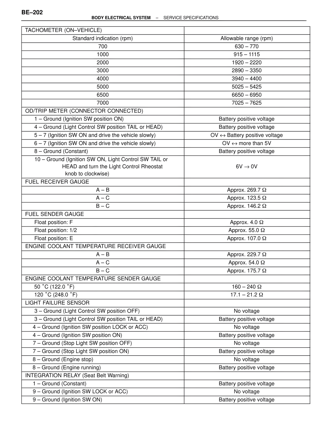
TACHOMETER (ON–VEHICLE)
Standard indication (rpm) Allowable range (rpm)
700 630 – 770
1000 915 – 1115
2000 1920 – 2220
3000 2890 – 3350
4000 3940 – 4400
5000 5025 – 5425
6500 6650 – 6950
7000 7025 – 7625
OD/TRIP METER (CONNECTOR CONNECTED)
1 – Ground (Ignition SW position ON) Battery positive voltage
4 – Ground (Light Control SW position TAIL or HEAD) Battery positive voltage
5 – 7 (Ignition SW ON and drive the vehicle slowly) 0V ↔ Battery positive voltage
6 – 7 (Ignition SW ON and drive the vehicle slowly) 0V ↔ more than 5V
8 – Ground (Constant) Battery positive voltage
10 – Ground (Ignition SW ON, Light Control SW TAIL or
HEAD and turn the Light Control Rheostat
knob to clockwise) 6V → 0V
FUEL RECEIVER GAUGE
A – B Approx. 269.7 Ω
A – C Approx. 123.5 Ω
B – C Approx. 146.2 Ω
FUEL SENDER GAUGE
Float position: F Approx. 4.0 Ω
Float position: 1/2 Approx. 55.0 Ω
Float position: E Approx. 107.0 Ω
ENGINE COOLANT TEMPERATURE RECEIVER GAUGE
A – B Approx. 229.7 Ω
A – C Approx. 54.0 Ω
B – C Approx. 175.7 Ω
ENGINE COOLANT TEMPERATURE SENDER GAUGE
50 °C (122.0 °F) 160 – 240 Ω
120 °C (248.0 °F) 17.1 – 21.2 Ω
LIGHT FAILURE SENSOR
3 – Ground (Light Control SW position OFF) No voltage
3 – Ground (Light Control SW position TAIL or HEAD) Battery positive voltage
4 – Ground (Ignition SW position LOCK or ACC) No voltage
4 – Ground (Ignition SW position ON) Battery positive voltage
7 – Ground (Stop Light SW position OFF) No voltage
7 – Ground (Stop Light SW position ON) Battery positive voltage
8 – Ground (Engine stop) No voltage
8 – Ground (Engine running) Battery positive voltage
INTEGRATION RELAY (Seat Belt Warning)
1 – Ground (Constant) Battery positive voltage
9 – Ground (Ignition SW LOCK or ACC) No voltage
9 – Ground (Ignition SW ON) Battery positive voltage