100%
BODY ELECTRICAL SYSTEM – COMBINATION METER
BE–55
SEAT BELT WARNING INSPECTION
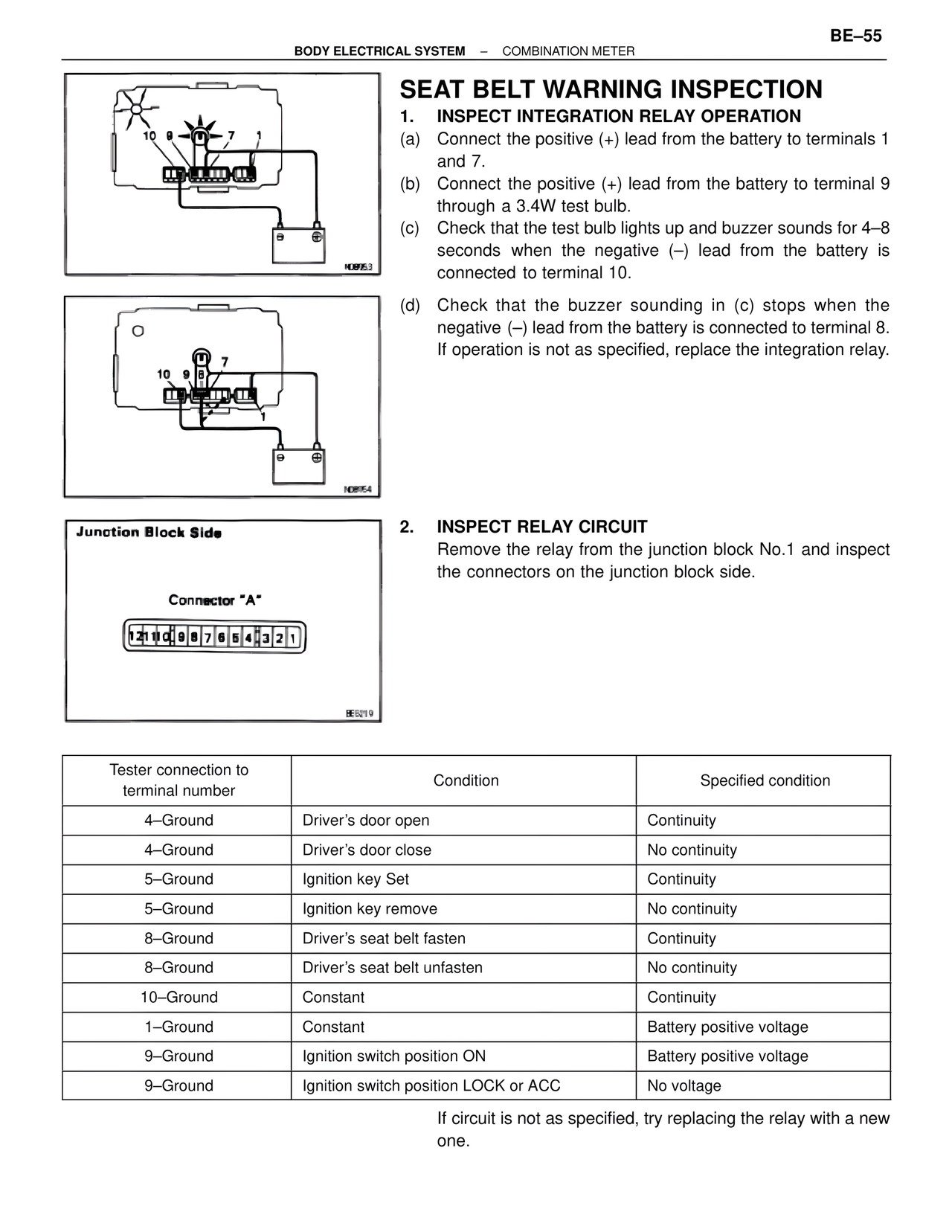
1. INSPECT INTEGRATION RELAY OPERATION
(a) Connect the positive (+) lead from the battery to terminals 1 and 7.
(b) Connect the positive (+) lead from the battery to terminal 9 through a 3.4W test bulb.
(c) Check that the test bulb lights up and buzzer sounds for 4–8 seconds when the negative (–) lead from the battery is connected to terminal 10.
(d) Check that the buzzer sounding in (c) stops when the negative (–) lead from the battery is connected to terminal 8. If operation is not as specified, replace the integration relay.
N08953
N08954
Junction Block Side
Connector "A"
12 11 10 9 8 7 6 5 4 3 2 1
BE6219
2. INSPECT RELAY CIRCUIT
Remove the relay from the junction block No.1 and inspect the connectors on the junction block side.
Tester connection to terminal number | Condition | Specified condition
4–Ground | Driver's door open | Continuity
4–Ground | Driver's door close | No continuity
5–Ground | Ignition key Set | Continuity
5–Ground | Ignition key remove | No continuity
8–Ground | Driver's seat belt fasten | Continuity
8–Ground | Driver's seat belt unfasten | No continuity
10–Ground | Constant | Continuity
1–Ground | Constant | Battery positive voltage
9–Ground | Ignition switch position ON | Battery positive voltage
9–Ground | Ignition switch position LOCK or ACC | No voltage
If circuit is not as specified, try replacing the relay with a new one.