Page text (OCR transcript)
BO-47
BODY – INSTRUMENT PANEL

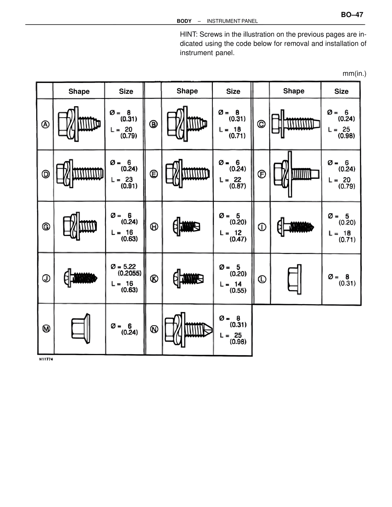
HINT: Screws in the illustration on the previous pages are indicated using the code below for removal and installation of instrument panel.

mm(in.)

Shape    Size    Shape    Size    Shape    Size

A    Ø = 8 (0.31)    B    Ø = 8 (0.31)    C    Ø = 6 (0.24)
     L = 20 (0.79)         L = 18 (0.71)         L = 25 (0.98)

D    Ø = 6 (0.24)    E    Ø = 6 (0.24)    F    Ø = 6 (0.24)
     L = 23 (0.91)         L = 22 (0.87)         L = 20 (0.79)

G    Ø = 6 (0.24)    H    Ø = 5 (0.20)    I    Ø = 5 (0.20)
     L = 16 (0.63)         L = 12 (0.47)         L = 18 (0.71)

J    Ø = 5.22 (0.2055)    K    Ø = 5 (0.20)    L    Ø = 8 (0.31)
     L = 16 (0.63)              L = 14 (0.55)

M    Ø = 6 (0.24)    N    Ø = 8 (0.31)
                              L = 25 (0.98)

N11774