100%
(k) Temporarily install the 3 bolts holding the delivery pipe to the
intake manifold.
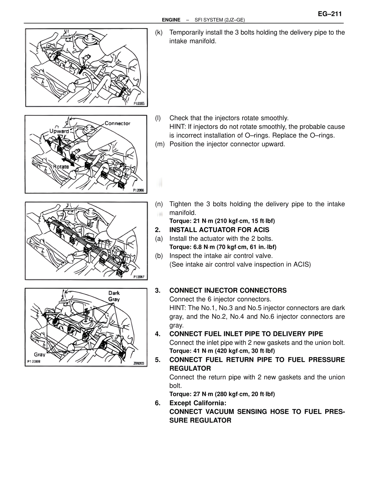
(l) Check that the injectors rotate smoothly.
HINT: If injectors do not rotate smoothly, the probable cause
is incorrect installation of O–rings. Replace the O–rings.
(m) Position the injector connector upward.
Connector
Upward
Rotate
(n) Tighten the 3 bolts holding the delivery pipe to the intake
manifold.
Torque: 21 N·m (210 kgf·cm, 15 ft·lbf)
2. INSTALL ACTUATOR FOR ACIS
(a) Install the actuator with the 2 bolts.
Torque: 6.8 N·m (70 kgf·cm, 61 in.·lbf)
(b) Inspect the intake air control valve.
(See intake air control valve inspection in ACIS)
Dark
Gray
3. CONNECT INJECTOR CONNECTORS
Connect the 6 injector connectors.
HINT: The No.1, No.3 and No.5 injector connectors are dark
gray, and the No.2, No.4 and No.6 injector connectors are
gray.
4. CONNECT FUEL INLET PIPE TO DELIVERY PIPE
Connect the inlet pipe with 2 new gaskets and the union bolt.
Torque: 41 N·m (420 kgf·cm, 30 ft·lbf)
5. CONNECT FUEL RETURN PIPE TO FUEL PRESSURE
REGULATOR
Connect the return pipe with 2 new gaskets and the union
bolt.
Torque: 27 N·m (280 kgf·cm, 20 ft·lbf)
6. Except California:
CONNECT VACUUM SENSING HOSE TO FUEL PRES-
SURE REGULATOR
Gray
P12068