100%
EG–212
ENGINE – SFI SYSTEM (2JZ–GE)
R
No.2
F
No.1
P12069
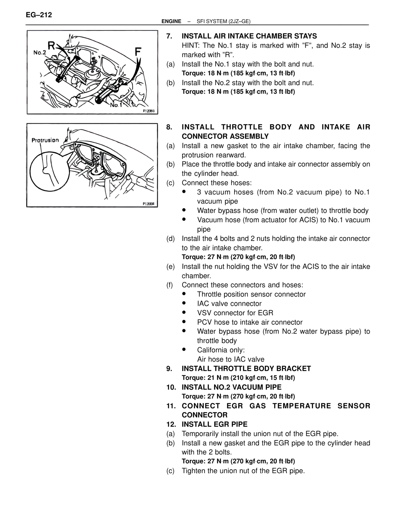
7. INSTALL AIR INTAKE CHAMBER STAYS
HINT: The No.1 stay is marked with "F", and No.2 stay is
marked with "R".
(a) Install the No.1 stay with the bolt and nut.
Torque: 18 N·m (185 kgf·cm, 13 ft·lbf)
(b) Install the No.2 stay with the bolt and nut.
Torque: 18 N·m (185 kgf·cm, 13 ft·lbf)
Protrusion
P12004
8. INSTALL THROTTLE BODY AND INTAKE AIR
CONNECTOR ASSEMBLY
(a) Install a new gasket to the air intake chamber, facing the
protrusion rearward.
(b) Place the throttle body and intake air connector assembly on
the cylinder head.
(c) Connect these hoses:
• 3 vacuum hoses (from No.2 vacuum pipe) to No.1
vacuum pipe
• Water bypass hose (from water outlet) to throttle body
• Vacuum hose (from actuator for ACIS) to No.1 vacuum
pipe
(d) Install the 4 bolts and 2 nuts holding the intake air connector
to the air intake chamber.
Torque: 27 N·m (270 kgf·cm, 20 ft·lbf)
(e) Install the nut holding the VSV for the ACIS to the air intake
chamber.
(f) Connect these connectors and hoses:
• Throttle position sensor connector
• IAC valve connector
• VSV connector for EGR
• PCV hose to intake air connector
• Water bypass hose (from No.2 water bypass pipe) to
throttle body
• California only:
Air hose to IAC valve
9. INSTALL THROTTLE BODY BRACKET
Torque: 21 N·m (210 kgf·cm, 15 ft·lbf)
10. INSTALL NO.2 VACUUM PIPE
Torque: 27 N·m (270 kgf·cm, 20 ft·lbf)
11. CONNECT EGR GAS TEMPERATURE SENSOR
CONNECTOR
12. INSTALL EGR PIPE
(a) Temporarily install the union nut of the EGR pipe.
(b) Install a new gasket and the EGR pipe to the cylinder head
with the 2 bolts.
Torque: 27 N·m (270 kgf·cm, 20 ft·lbf)
(c) Tighten the union nut of the EGR pipe.