100%
RS–98
SUPPLEMENTAL RESTRAINT SYSTEM – TROUBLESHOOTING
Tc Terminal Circuit
CIRCUIT DESCRIPTION
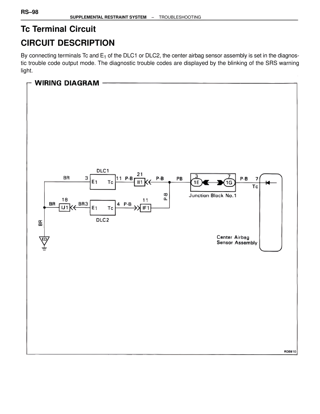
By connecting terminals Tc and E1 of the DLC1 or DLC2, the center airbag sensor assembly is set in the diagnostic trouble code output mode. The diagnostic trouble codes are displayed by the blinking of the SRS warning light.
WIRING DIAGRAM
DLC1
BR 3
E1 Tc 11 P-B 21
II1 P-B PB
3
1E 1G P-B 7
Tc
Junction Block No.1
BR 18
IJ1 BR3 E1 Tc 4 P-B 11
IF1
DLC2
PB
BR
ED
Center Airbag
Sensor Assembly
R05910