100%
EG–150
ENGINE – TURBOCHARGER SYSTEM (2JZ–GTE)
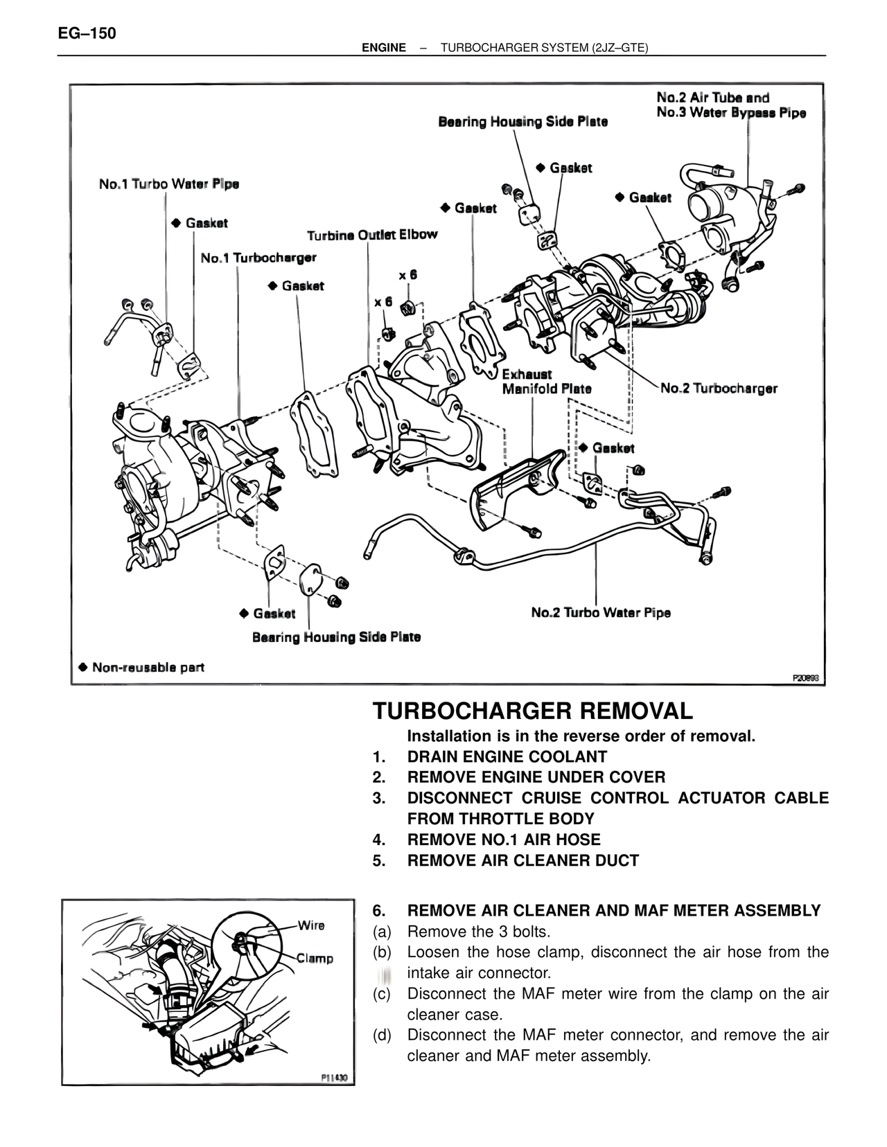
No.2 Air Tube and
No.3 Water Bypass Pipe
Bearing Housing Side Plate
◆ Gasket
◆ Gasket
No.1 Turbo Water Pipe
◆ Gasket
◆ Gasket
Turbine Outlet Elbow
No.1 Turbocharger
◆ Gasket
x 6
x 6
Exhaust
Manifold Plate
No.2 Turbocharger
◆ Gasket
No.2 Turbo Water Pipe
◆ Gasket
Bearing Housing Side Plate
◆ Non-reusable part
P20893
TURBOCHARGER REMOVAL
Installation is in the reverse order of removal.
1. DRAIN ENGINE COOLANT
2. REMOVE ENGINE UNDER COVER
3. DISCONNECT CRUISE CONTROL ACTUATOR CABLE FROM THROTTLE BODY
4. REMOVE NO.1 AIR HOSE
5. REMOVE AIR CLEANER DUCT
6. REMOVE AIR CLEANER AND MAF METER ASSEMBLY
(a) Remove the 3 bolts.
(b) Loosen the hose clamp, disconnect the air hose from the intake air connector.
(c) Disconnect the MAF meter wire from the clamp on the air cleaner case.
(d) Disconnect the MAF meter connector, and remove the air cleaner and MAF meter assembly.
Wire
Clamp
P11430