AC–27
AIR CONDITIONING SYSTEM – TROUBLESHOOTING
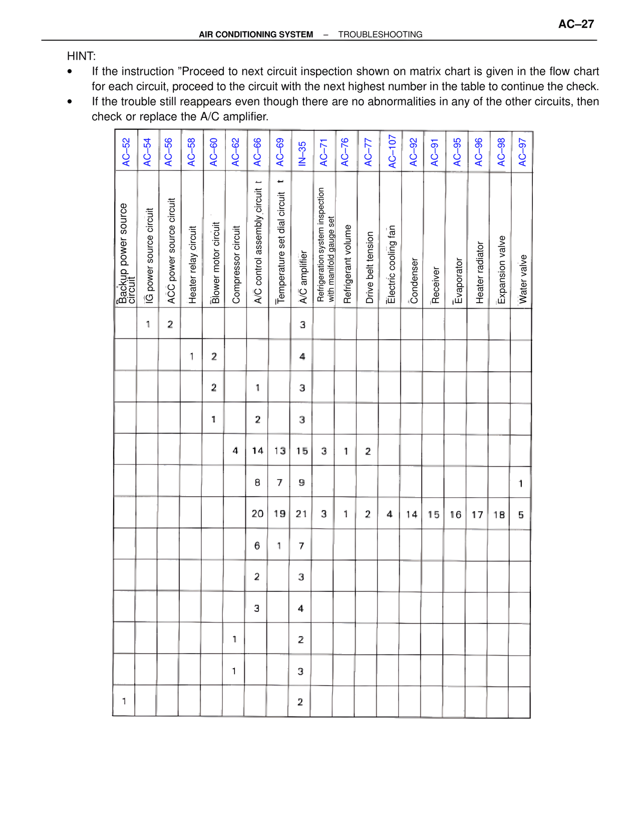
HINT:
• If the instruction "Proceed to next circuit inspection shown on matrix chart is given in the flow chart for each circuit, proceed to the circuit with the next highest number in the table to continue the check.
• If the trouble still reappears even though there are no abnormalities in any of the other circuits, then check or replace the A/C amplifier.
Column Headers (left to right):
AC–52
AC–54
AC–56
AC–58
AC–60
AC–62
AC–66
AC–69
IN–35
AC–71
AC–76
AC–77
AC–107
AC–92
AC–91
AC–95
AC–96
AC–98
AC–97
Row Labels (top to bottom):
Backup power source circuit
IG power source circuit
ACC power source circuit
Heater relay circuit
Blower motor circuit
Compressor circuit
A/C control assembly circuit t
Temperature set dial circuit t
A/C amplifier
Refrigeration system inspection with manifold gauge set
Refrigerant volume
Drive belt tension
Electric cooling fan
Condenser
Receiver
Evaporator
Heater radiator
Expansion valve
Water valve
Table Data (row by row):
Row 1: IG power source circuit=1, ACC power source circuit=2, A/C amplifier=3
Row 2: Heater relay circuit=1, Blower motor circuit=2, A/C amplifier=4
Row 3: Blower motor circuit=2, Compressor circuit=1, A/C amplifier=3
Row 4: Blower motor circuit=1, A/C control assembly circuit=2, A/C amplifier=3
Row 5: Compressor circuit=4, A/C control assembly circuit=14, Temperature set dial circuit=13, A/C amplifier=15, Refrigeration system inspection=3, Refrigerant volume=1, Drive belt tension=2
Row 6: A/C control assembly circuit=8, Temperature set dial circuit=7, A/C amplifier=9, Water valve=1
Row 7: A/C control assembly circuit=20, Temperature set dial circuit=19, A/C amplifier=21, Refrigeration system inspection=3, Refrigerant volume=1, Drive belt tension=2, Electric cooling fan=4, Condenser=14, Receiver=15, Evaporator=16, Heater radiator=17, Expansion valve=18, Water valve=5
Row 8: A/C control assembly circuit=6, Temperature set dial circuit=1, A/C amplifier=7
Row 9: A/C control assembly circuit=2, A/C amplifier=3
Row 10: A/C control assembly circuit=3, A/C amplifier=4
Row 11: Compressor circuit=1, A/C amplifier=2
Row 12: Compressor circuit=1, A/C amplifier=3
Row 13: Backup power source circuit=1, A/C amplifier=2