AC–31
AIR CONDITIONING SYSTEM – TROUBLESHOOTING
INSPECTION PROCEDURE
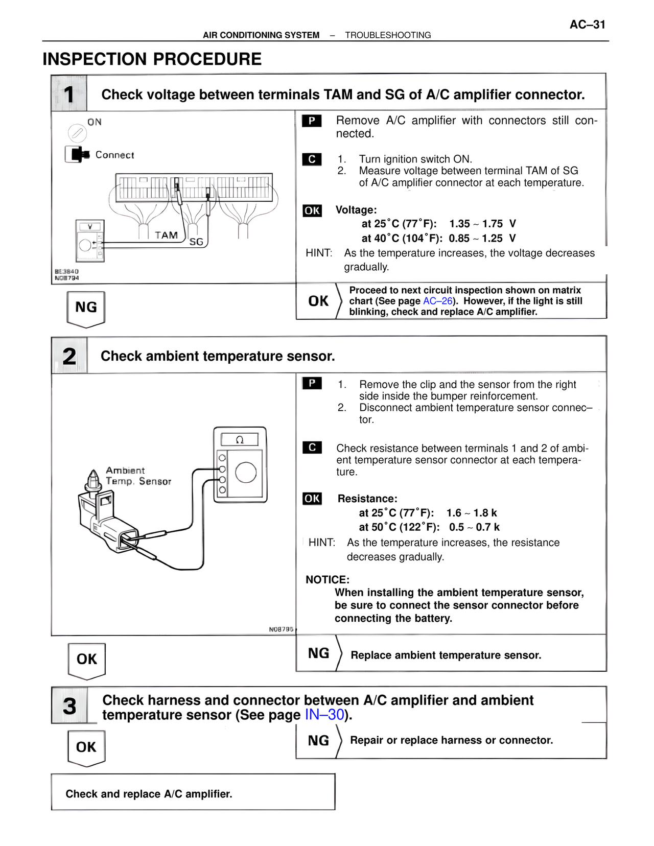
1 Check voltage between terminals TAM and SG of A/C amplifier connector.
ON
Connect
TAM SG
SE3840
NC8794
P Remove A/C amplifier with connectors still connected.
C 1. Turn ignition switch ON.
2. Measure voltage between terminal TAM of SG of A/C amplifier connector at each temperature.
OK Voltage:
at 25°C (77°F): 1.35 ~ 1.75 V
at 40°C (104°F): 0.85 ~ 1.25 V
HINT: As the temperature increases, the voltage decreases gradually.
NG
OK Proceed to next circuit inspection shown on matrix chart (See page AC–26). However, if the light is still blinking, check and replace A/C amplifier.
2 Check ambient temperature sensor.
Ambient
Temp. Sensor
NC8795
P 1. Remove the clip and the sensor from the right side inside the bumper reinforcement.
2. Disconnect ambient temperature sensor connector.
C Check resistance between terminals 1 and 2 of ambient temperature sensor connector at each temperature.
OK Resistance:
at 25°C (77°F): 1.6 ~ 1.8 k
at 50°C (122°F): 0.5 ~ 0.7 k
HINT: As the temperature increases, the resistance decreases gradually.
NOTICE:
When installing the ambient temperature sensor, be sure to connect the sensor connector before connecting the battery.
OK
NG Replace ambient temperature sensor.
3 Check harness and connector between A/C amplifier and ambient temperature sensor (See page IN–30).
OK
NG Repair or replace harness or connector.
Check and replace A/C amplifier.