AC–35
AIR CONDITIONING SYSTEM – TROUBLESHOOTING
INSPECTION PROCEDURE
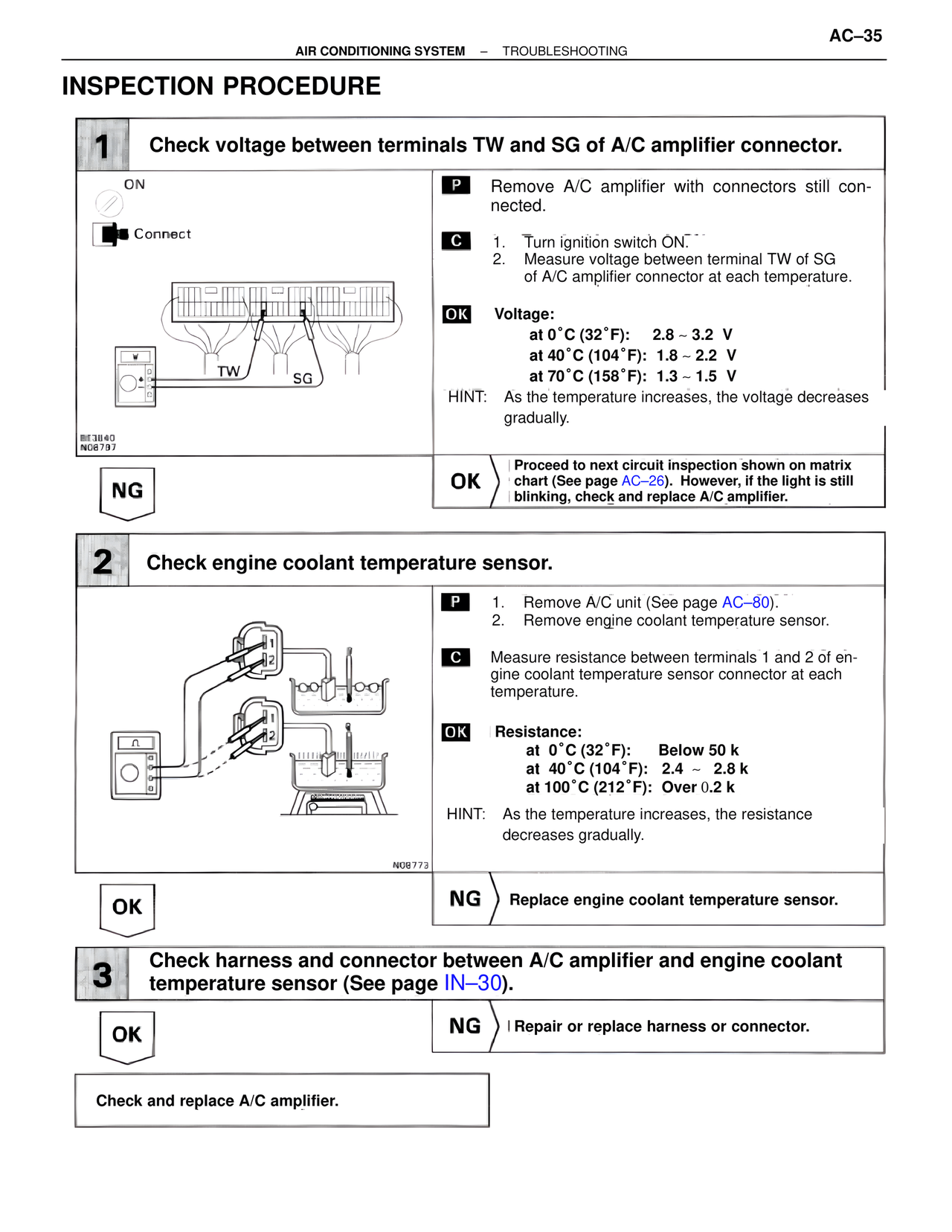
1 Check voltage between terminals TW and SG of A/C amplifier connector.
ON
Connect
TW SG
BE3840
N08797
P Remove A/C amplifier with connectors still connected.
C 1. Turn ignition switch ON.
2. Measure voltage between terminal TW of SG of A/C amplifier connector at each temperature.
OK Voltage:
at 0˚C (32˚F): 2.8 ~ 3.2 V
at 40˚C (104˚F): 1.8 ~ 2.2 V
at 70˚C (158˚F): 1.3 ~ 1.5 V
HINT: As the temperature increases, the voltage decreases gradually.
NG
OK Proceed to next circuit inspection shown on matrix chart (See page AC–26). However, if the light is still blinking, check and replace A/C amplifier.
2 Check engine coolant temperature sensor.
N08773
P 1. Remove A/C unit (See page AC–80).
2. Remove engine coolant temperature sensor.
C Measure resistance between terminals 1 and 2 of engine coolant temperature sensor connector at each temperature.
OK Resistance:
at 0˚C (32˚F): Below 50 k
at 40˚C (104˚F): 2.4 ~ 2.8 k
at 100˚C (212˚F): Over 0.2 k
HINT: As the temperature increases, the resistance decreases gradually.
OK
NG Replace engine coolant temperature sensor.
3 Check harness and connector between A/C amplifier and engine coolant temperature sensor (See page IN–30).
OK
NG Repair or replace harness or connector.
Check and replace A/C amplifier.