AC–37
AIR CONDITIONING SYSTEM – TROUBLESHOOTING
INSPECTION PROCEDURE
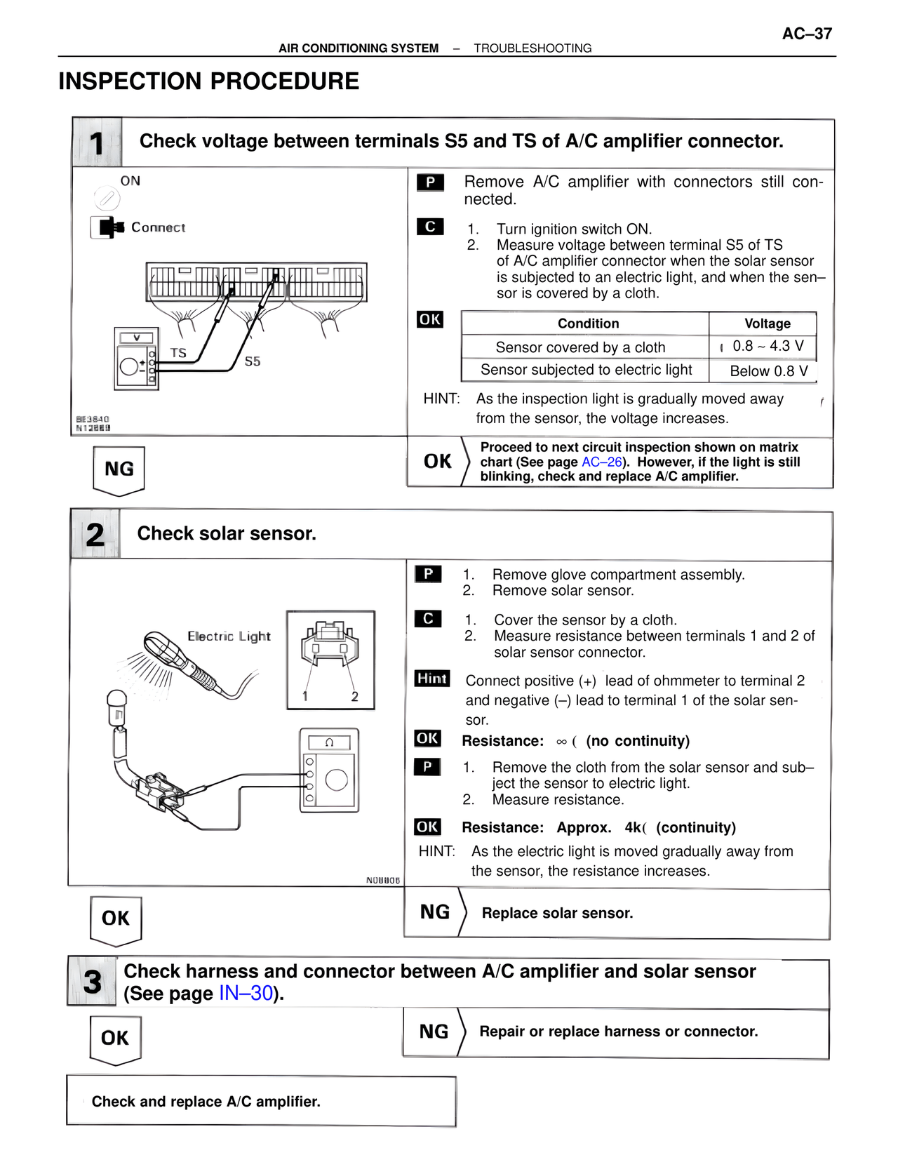
1 Check voltage between terminals S5 and TS of A/C amplifier connector.
ON
Connect
TS S5
8E3840
N12669
P Remove A/C amplifier with connectors still connected.
C 1. Turn ignition switch ON.
2. Measure voltage between terminal S5 of TS of A/C amplifier connector when the solar sensor is subjected to an electric light, and when the sensor is covered by a cloth.
OK
Condition Voltage
Sensor covered by a cloth 0.8 ~ 4.3 V
Sensor subjected to electric light Below 0.8 V
HINT: As the inspection light is gradually moved away from the sensor, the voltage increases.
NG
OK Proceed to next circuit inspection shown on matrix chart (See page AC–26). However, if the light is still blinking, check and replace A/C amplifier.
2 Check solar sensor.
Electric Light
1 2
N08806
P 1. Remove glove compartment assembly.
2. Remove solar sensor.
C 1. Cover the sensor by a cloth.
2. Measure resistance between terminals 1 and 2 of solar sensor connector.
Hint Connect positive (+) lead of ohmmeter to terminal 2 and negative (–) lead to terminal 1 of the solar sensor.
OK Resistance: ∞ ( (no continuity)
P 1. Remove the cloth from the solar sensor and subject the sensor to electric light.
2. Measure resistance.
OK Resistance: Approx. 4k( (continuity)
HINT: As the electric light is moved gradually away from the sensor, the resistance increases.
OK
NG Replace solar sensor.
3 Check harness and connector between A/C amplifier and solar sensor (See page IN–30).
OK
NG Repair or replace harness or connector.
Check and replace A/C amplifier.