AC–43
AIR CONDITIONING SYSTEM – TROUBLESHOOTING
INSPECTION PROCEDURE
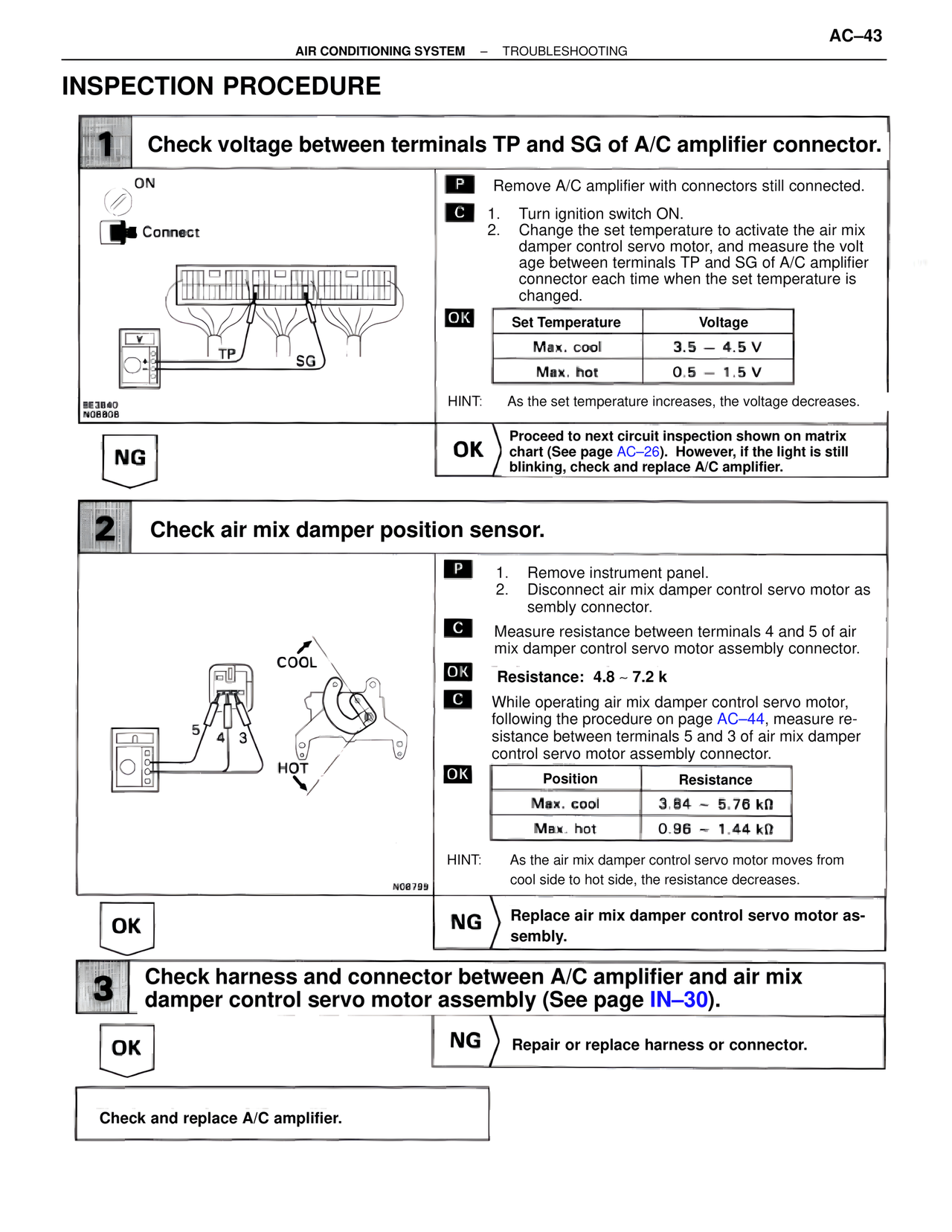
1 Check voltage between terminals TP and SG of A/C amplifier connector.
ON
Connect
TP SG
BE3840
N08808
P Remove A/C amplifier with connectors still connected.
C 1. Turn ignition switch ON.
2. Change the set temperature to activate the air mix damper control servo motor, and measure the voltage between terminals TP and SG of A/C amplifier connector each time when the set temperature is changed.
OK
Set Temperature Voltage
Max. cool 3.5 – 4.5 V
Max. hot 0.5 – 1.5 V
HINT: As the set temperature increases, the voltage decreases.
NG
OK Proceed to next circuit inspection shown on matrix chart (See page AC–26). However, if the light is still blinking, check and replace A/C amplifier.
2 Check air mix damper position sensor.
COOL
5 4 3
HOT
N08799
P 1. Remove instrument panel.
2. Disconnect air mix damper control servo motor assembly connector.
C Measure resistance between terminals 4 and 5 of air mix damper control servo motor assembly connector.
OK Resistance: 4.8 ~ 7.2 k
C While operating air mix damper control servo motor, following the procedure on page AC–44, measure resistance between terminals 5 and 3 of air mix damper control servo motor assembly connector.
OK
Position Resistance
Max. cool 3.84 ~ 5.76 kΩ
Max. hot 0.96 ~ 1.44 kΩ
HINT: As the air mix damper control servo motor moves from cool side to hot side, the resistance decreases.
OK
NG Replace air mix damper control servo motor assembly.
3 Check harness and connector between A/C amplifier and air mix damper control servo motor assembly (See page IN–30).
OK
NG Repair or replace harness or connector.
Check and replace A/C amplifier.