AC–51
AIR CONDITIONING SYSTEM – TROUBLESHOOTING
INSPECTION PROCEDURE
1 Actuator check.
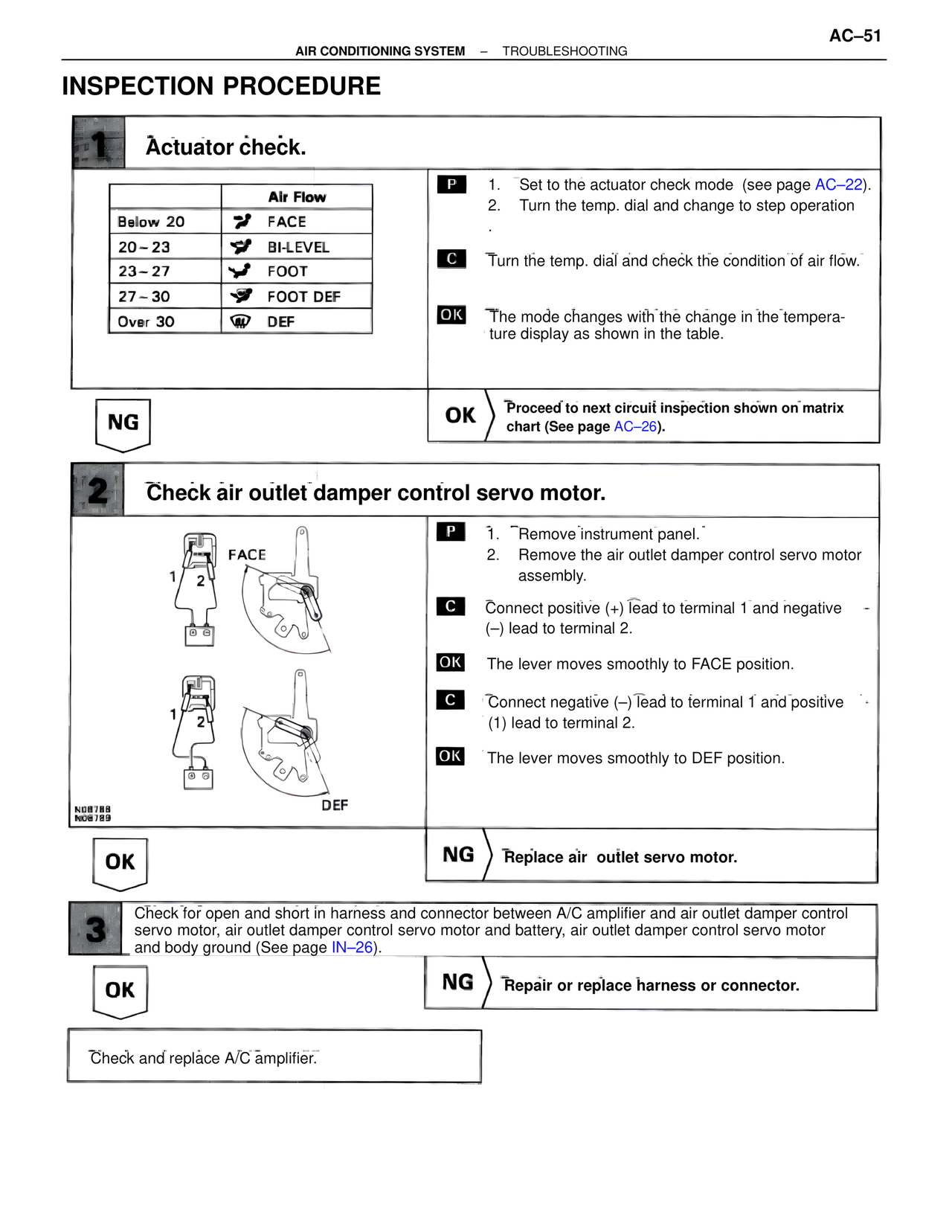
Air Flow
Below 20 FACE
20 – 23 BI-LEVEL
23 – 27 FOOT
27 – 30 FOOT DEF
Over 30 DEF
P 1. Set to the actuator check mode (see page AC–22).
2. Turn the temp. dial and change to step operation.
C Turn the temp. dial and check the condition of air flow.
OK The mode changes with the change in the temperature display as shown in the table.
NG
OK Proceed to next circuit inspection shown on matrix chart (See page AC–26).
2 Check air outlet damper control servo motor.
FACE
1 2
1 2
NO8788
NO8789 DEF
P 1. Remove instrument panel.
2. Remove the air outlet damper control servo motor assembly.
C Connect positive (+) lead to terminal 1 and negative (–) lead to terminal 2.
OK The lever moves smoothly to FACE position.
C Connect negative (–) lead to terminal 1 and positive (1) lead to terminal 2.
OK The lever moves smoothly to DEF position.
OK
NG Replace air outlet servo motor.
3 Check for open and short in harness and connector between A/C amplifier and air outlet damper control servo motor, air outlet damper control servo motor and battery, air outlet damper control servo motor and body ground (See page IN–26).
OK
NG Repair or replace harness or connector.
Check and replace A/C amplifier.