AC–54
AIR CONDITIONING SYSTEM – TROUBLESHOOTING
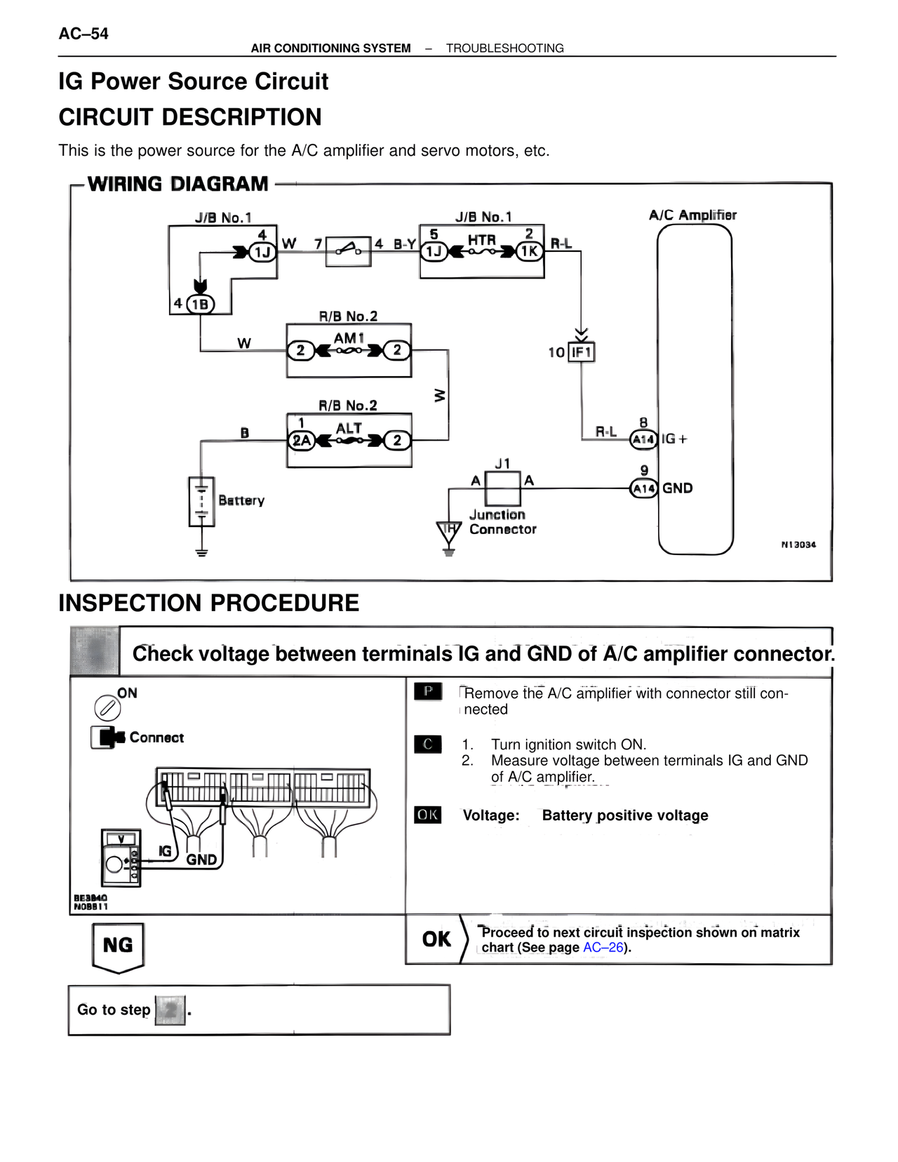
IG Power Source Circuit
CIRCUIT DESCRIPTION
This is the power source for the A/C amplifier and servo motors, etc.
WIRING DIAGRAM
J/B No.1
4
1J
W
7
4 B-Y
J/B No.1
5
1J
HTR
2
1K
R-L
A/C Amplifier
4
1B
R/B No.2
W
2
AM1
2
10 IF1
R/B No.2
B
1
2A
ALT
2
R-L
8
A14
IG +
W
J1
A
A
9
A14
GND
Battery
Junction
Connector
N13034
INSPECTION PROCEDURE
Check voltage between terminals IG and GND of A/C amplifier connector.
ON
Connect
IG GND
BE3840
N08811
P
Remove the A/C amplifier with connector still connected
C
1. Turn ignition switch ON.
2. Measure voltage between terminals IG and GND of A/C amplifier.
OK Voltage: Battery positive voltage
NG
OK Proceed to next circuit inspection shown on matrix chart (See page AC–26).
Go to step .