AC–60
AIR CONDITIONING SYSTEM – TROUBLESHOOTING
Blower Motor Circuit
CIRCUIT DESCRIPTION
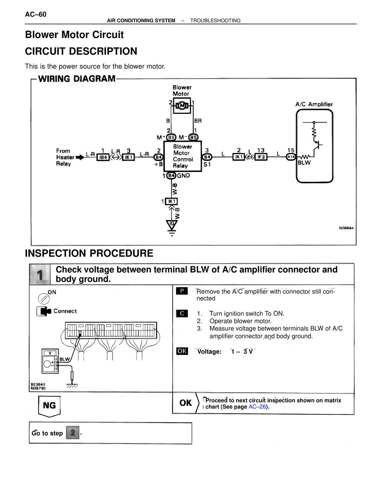
This is the power source for the blower motor.
WIRING DIAGRAM
Blower
Motor
2 1
B BR
2 1
M+ B5 M- B5
Blower
Motor
Control
Relay
From
Heater → L-R 1 L-R 3 L-R 2
Relay B4 IK1 B4
+B
1 B4 GND
W-B
1 K1
W-B
3 L 2 L 13 L 15
B4 S1 IK1 IF3 A16
BLW
A/C Amplifier
BLW
NO8844
INSPECTION PROCEDURE
1 Check voltage between terminal BLW of A/C amplifier connector and
body ground.
ON
Connect
V
BLW
BE3840
NO8790
P Remove the A/C amplifier with connector still connected
C 1. Turn ignition switch To ON.
2. Operate blower motor.
3. Measure voltage between terminals BLW of A/C
amplifier connector and body ground.
OK Voltage: 1 – 3 V
NG OK Proceed to next circuit inspection shown on matrix
chart (See page AC–26).
Go to step 2 .