AT1-29
AT340E (2JZ-GE) AUTOMATIC TRANSMISSION – SHIFT LOCK SYSTEM
ELECTRONIC CONTROL COMPONENTS INSPECTION
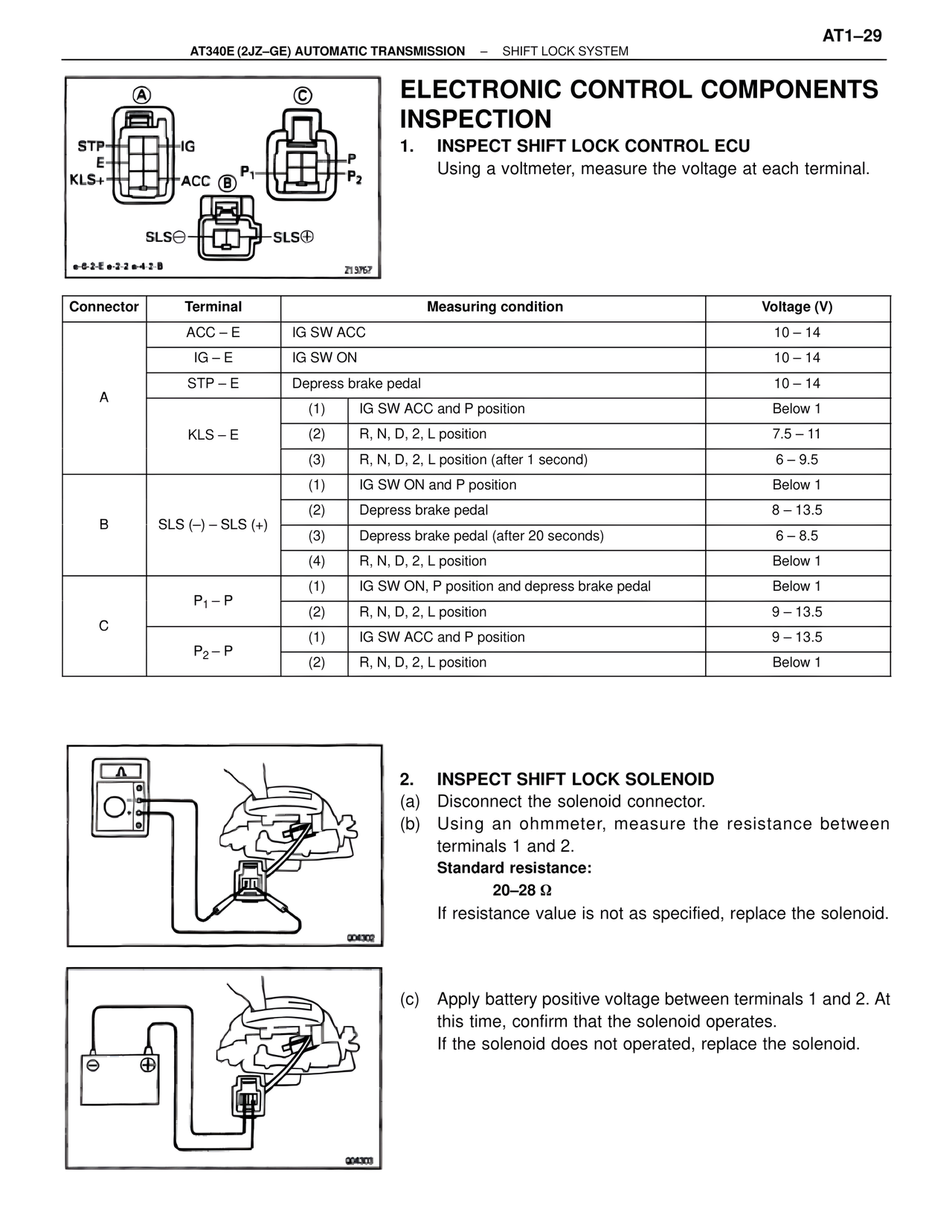
1. INSPECT SHIFT LOCK CONTROL ECU
Using a voltmeter, measure the voltage at each terminal.
Connector | Terminal | Measuring condition | Voltage (V)
A | ACC – E | IG SW ACC | 10 – 14
A | IG – E | IG SW ON | 10 – 14
A | STP – E | Depress brake pedal | 10 – 14
A | KLS – E | (1) IG SW ACC and P position | Below 1
A | KLS – E | (2) R, N, D, 2, L position | 7.5 – 11
A | KLS – E | (3) R, N, D, 2, L position (after 1 second) | 6 – 9.5
B | SLS (–) – SLS (+) | (1) IG SW ON and P position | Below 1
B | SLS (–) – SLS (+) | (2) Depress brake pedal | 8 – 13.5
B | SLS (–) – SLS (+) | (3) Depress brake pedal (after 20 seconds) | 6 – 8.5
B | SLS (–) – SLS (+) | (4) R, N, D, 2, L position | Below 1
C | P1 – P | (1) IG SW ON, P position and depress brake pedal | Below 1
C | P1 – P | (2) R, N, D, 2, L position | 9 – 13.5
C | P2 – P | (1) IG SW ACC and P position | 9 – 13.5
C | P2 – P | (2) R, N, D, 2, L position | Below 1
2. INSPECT SHIFT LOCK SOLENOID
(a) Disconnect the solenoid connector.
(b) Using an ohmmeter, measure the resistance between terminals 1 and 2.
Standard resistance:
20–28 Ω
If resistance value is not as specified, replace the solenoid.
(c) Apply battery positive voltage between terminals 1 and 2. At this time, confirm that the solenoid operates.
If the solenoid does not operated, replace the solenoid.