AT1–70
AT340E (2JZ–GE) AUTOMATIC TRANSMISSION – TROUBLESHOOTING
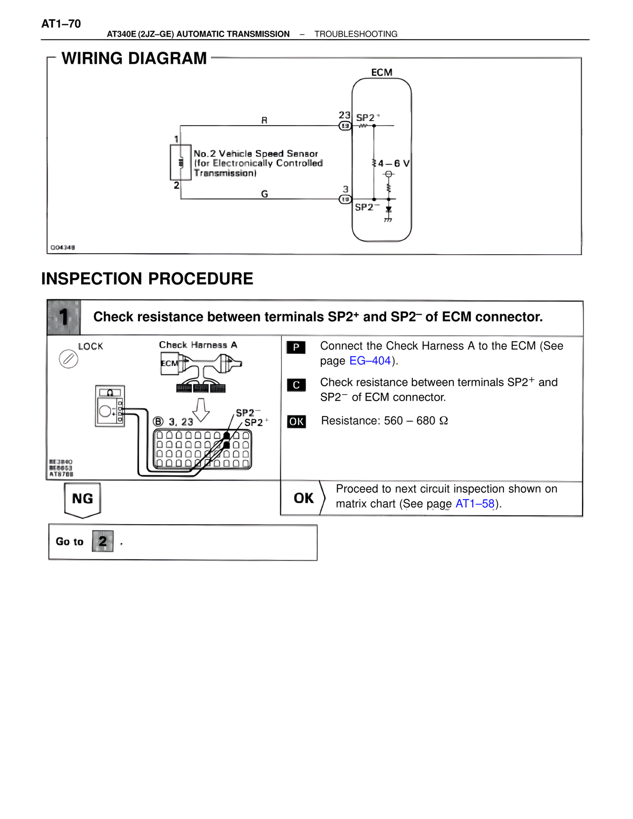
WIRING DIAGRAM
ECM
R
23 SP2+
19
1
No.2 Vehicle Speed Sensor
(for Electronically Controlled
Transmission)
2
4–6 V
G
3
19
SP2–
G04348
INSPECTION PROCEDURE
1 Check resistance between terminals SP2+ and SP2– of ECM connector.
LOCK Check Harness A
ECM
B 3, 23 SP2–
SP2+
BE3840
BE6653
AT8788
P Connect the Check Harness A to the ECM (See page EG–404).
C Check resistance between terminals SP2+ and SP2– of ECM connector.
OK Resistance: 560 – 680 Ω
NG OK Proceed to next circuit inspection shown on matrix chart (See page AT1–58).
Go to 2 .