AT1–80
AT340E (2JZ–GE) AUTOMATIC TRANSMISSION – TROUBLESHOOTING
INSPECTION PROCEDURE
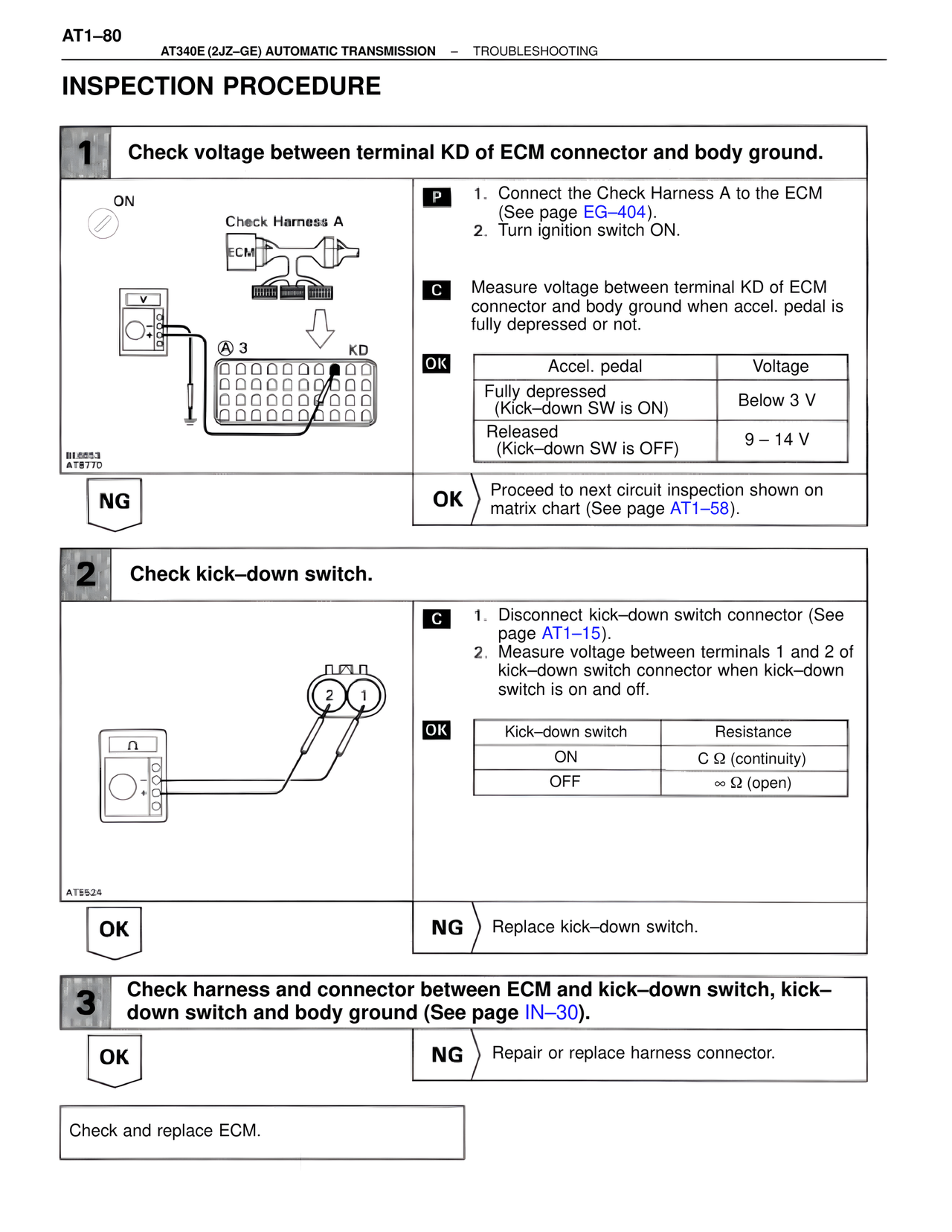
1 Check voltage between terminal KD of ECM connector and body ground.
ON
Check Harness A
ECM
P 1. Connect the Check Harness A to the ECM (See page EG–404).
2. Turn ignition switch ON.
C Measure voltage between terminal KD of ECM connector and body ground when accel. pedal is fully depressed or not.
OK
Accel. pedal | Voltage
Fully depressed (Kick–down SW is ON) | Below 3 V
Released (Kick–down SW is OFF) | 9 – 14 V
A 3 KD
BE6653
AT8770
NG
OK Proceed to next circuit inspection shown on matrix chart (See page AT1–58).
2 Check kick–down switch.
2 1
C 1. Disconnect kick–down switch connector (See page AT1–15).
2. Measure voltage between terminals 1 and 2 of kick–down switch connector when kick–down switch is on and off.
OK
Kick–down switch | Resistance
ON | C Ω (continuity)
OFF | ∞ Ω (open)
AT5524
OK
NG Replace kick–down switch.
3 Check harness and connector between ECM and kick–down switch, kick–down switch and body ground (See page IN–30).
OK
NG Repair or replace harness connector.
Check and replace ECM.