Stop Light Switch Circuit
CIRCUIT DESCRIPTION
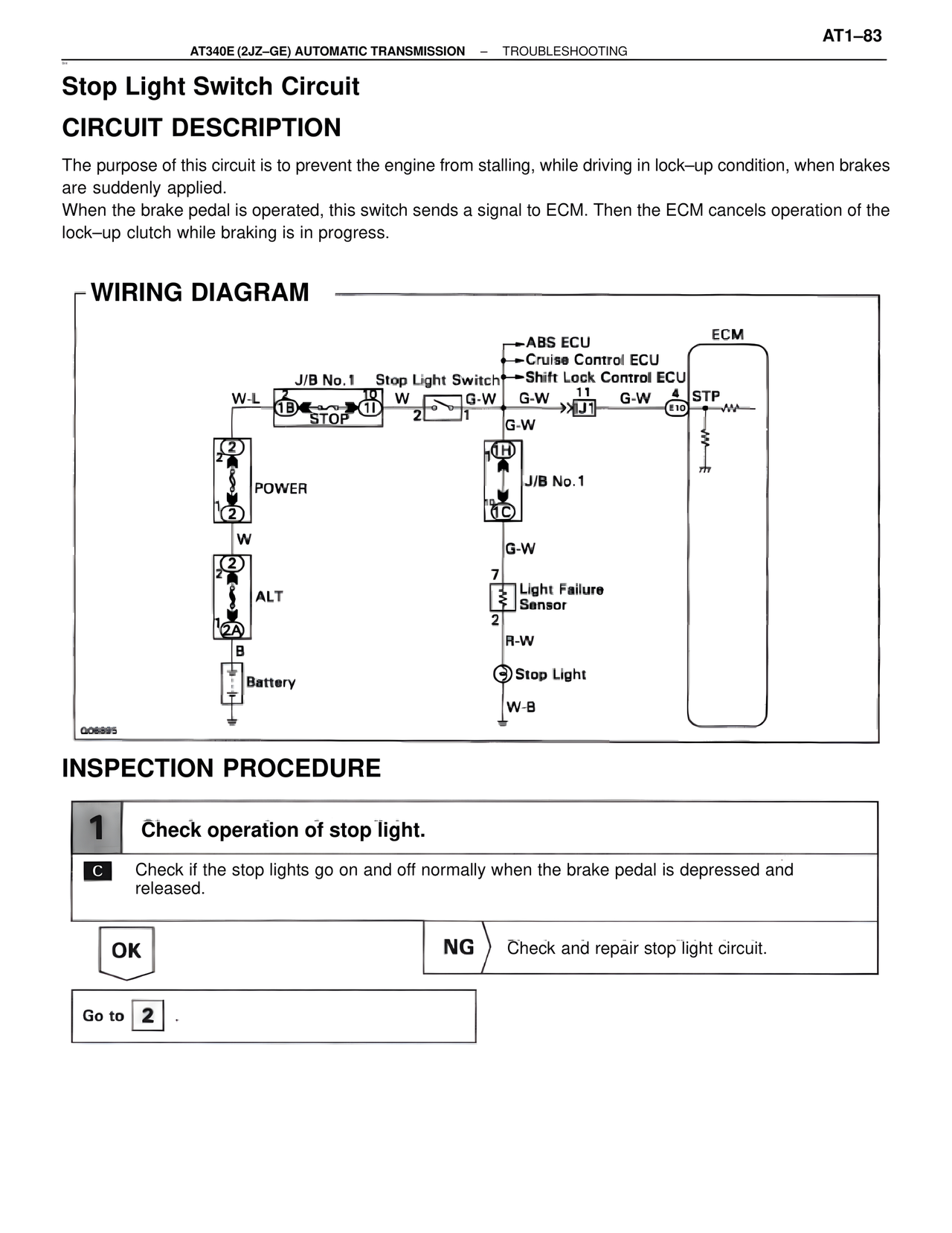
The purpose of this circuit is to prevent the engine from stalling, while driving in lock–up condition, when brakes are suddenly applied.
When the brake pedal is operated, this switch sends a signal to ECM. Then the ECM cancels operation of the lock–up clutch while braking is in progress.
WIRING DIAGRAM
ECM
·ABS ECU
·Cruise Control ECU
J/B No.1 Stop Light Switch·Shift Lock Control ECU
W-L 10 W G-W G-W 11 G-W 4 STP
1B 1I 2 1 J1 E10
STOP
G-W
2 0H
POWER J/B No.1
1 0C
2
W G-W
2
ALT 7 Light Failure
Sensor
1 2
2A
B R-W
Battery Stop Light
W-B
Q06895
INSPECTION PROCEDURE
1 Check operation of stop light.
C Check if the stop lights go on and off normally when the brake pedal is depressed and released.
OK NG Check and repair stop light circuit.
Go to 2 .