AT2–102
A340E (2JZ—GTE) AUTOMATIC TRANSMISSION – TROUBLESHOOTING
INSPECTION PROCEDURE
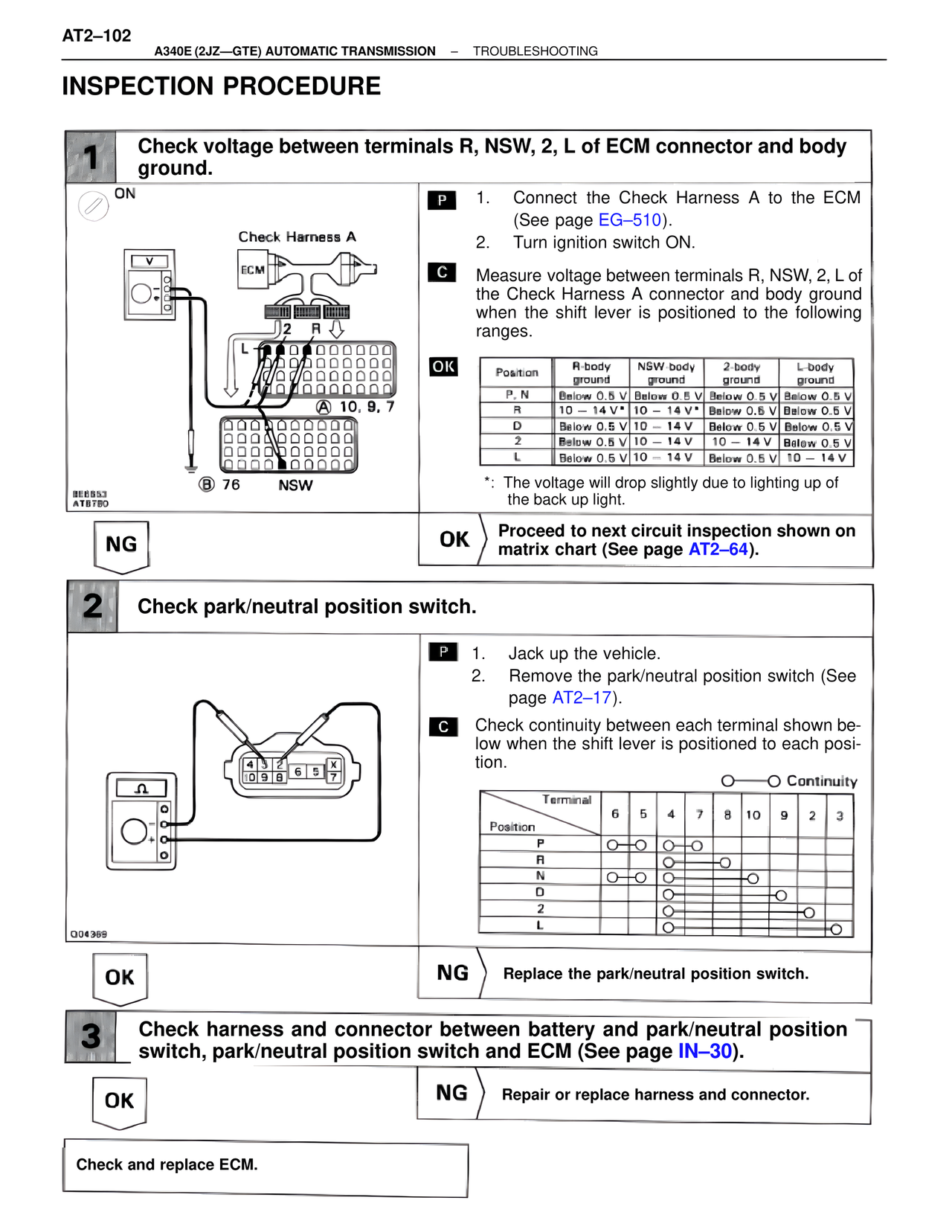
1 Check voltage between terminals R, NSW, 2, L of ECM connector and body ground.
ON
Check Harness A
ECM
2 R
L
A 10, 9, 7
BEB853
ATB780
B 76 NSW
P 1. Connect the Check Harness A to the ECM (See page EG–510).
2. Turn ignition switch ON.
C Measure voltage between terminals R, NSW, 2, L of the Check Harness A connector and body ground when the shift lever is positioned to the following ranges.
OK
Position | R-body ground | NSW-body ground | 2-body ground | L-body ground
P, N | Below 0.5 V | Below 0.5 V | Below 0.5 V | Below 0.5 V
R | 10 – 14 V* | 10 – 14 V* | Below 0.5 V | Below 0.5 V
D | Below 0.5 V | 10 – 14 V | Below 0.5 V | Below 0.5 V
2 | Below 0.5 V | 10 – 14 V | 10 – 14 V | Below 0.5 V
L | Below 0.5 V | 10 – 14 V | Below 0.5 V | 10 – 14 V
*: The voltage will drop slightly due to lighting up of the back up light.
NG OK Proceed to next circuit inspection shown on matrix chart (See page AT2–64).
2 Check park/neutral position switch.
4 3 2
10 9 8
6 5 x
7
Q04369
P 1. Jack up the vehicle.
2. Remove the park/neutral position switch (See page AT2–17).
C Check continuity between each terminal shown below when the shift lever is positioned to each position.
O——O Continuity
Terminal
Position | 6 | 5 | 4 | 7 | 8 | 10 | 9 | 2 | 3
P | O—O | | O—O | | | | | |
R | | O | | | O | | | |
N | O—O | | O | | | O | | |
D | | | | | | | O | |
2 | | | O | | | | | O |
L | | | O | | | | | | O
OK NG Replace the park/neutral position switch.
3 Check harness and connector between battery and park/neutral position switch, park/neutral position switch and ECM (See page IN–30).
OK NG Repair or replace harness and connector.
Check and replace ECM.