AT2–73
A340E (2JZ—GTE) AUTOMATIC TRANSMISSION – TROUBLESHOOTING
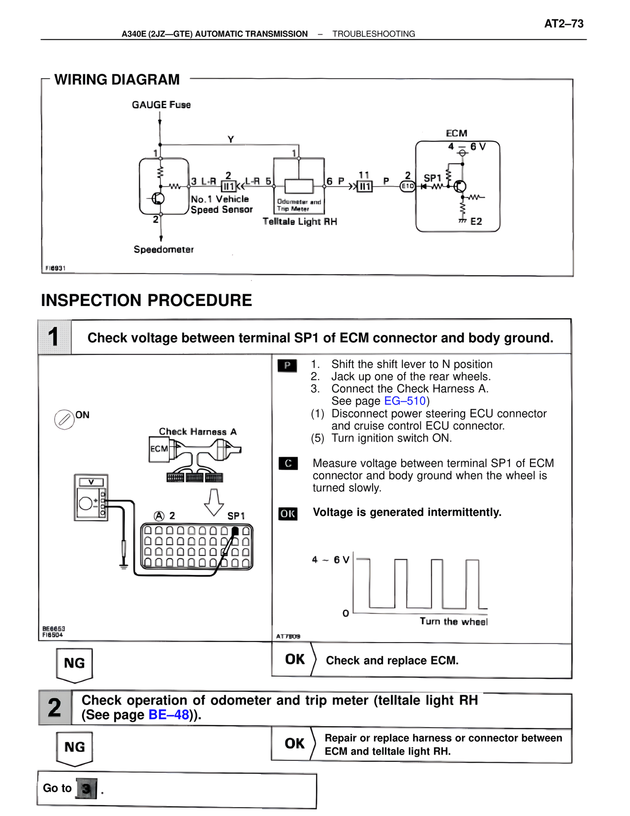
WIRING DIAGRAM
GAUGE Fuse
Y
ECM
4 ~ 6 V
1
3 L-R 2 L-R 5
II1 6 P 11 P 2
II1 SP1
E10
No. 1 Vehicle
Speed Sensor
Odometer and
Trip Meter
Telltale Light RH
2
E2
Speedometer
FI6931
INSPECTION PROCEDURE
1 Check voltage between terminal SP1 of ECM connector and body ground.
ON
Check Harness A
ECM
V
A 2 SP1
BE6653
FI6504
P 1. Shift the shift lever to N position
2. Jack up one of the rear wheels.
3. Connect the Check Harness A.
See page EG–510)
(1) Disconnect power steering ECU connector
and cruise control ECU connector.
(5) Turn ignition switch ON.
C Measure voltage between terminal SP1 of ECM
connector and body ground when the wheel is
turned slowly.
OK Voltage is generated intermittently.
4 ~ 6 V
O
Turn the wheel
AT7809
NG OK Check and replace ECM.
2 Check operation of odometer and trip meter (telltale light RH
(See page BE–48)).
NG OK Repair or replace harness or connector between
ECM and telltale light RH.
Go to 3 .