AT2–79
A340E (2JZ—GTE) AUTOMATIC TRANSMISSION – TROUBLESHOOTING
DTC 61 No.2 Vehicle Speed Sensor Circuit
CIRCUIT DESCRIPTION
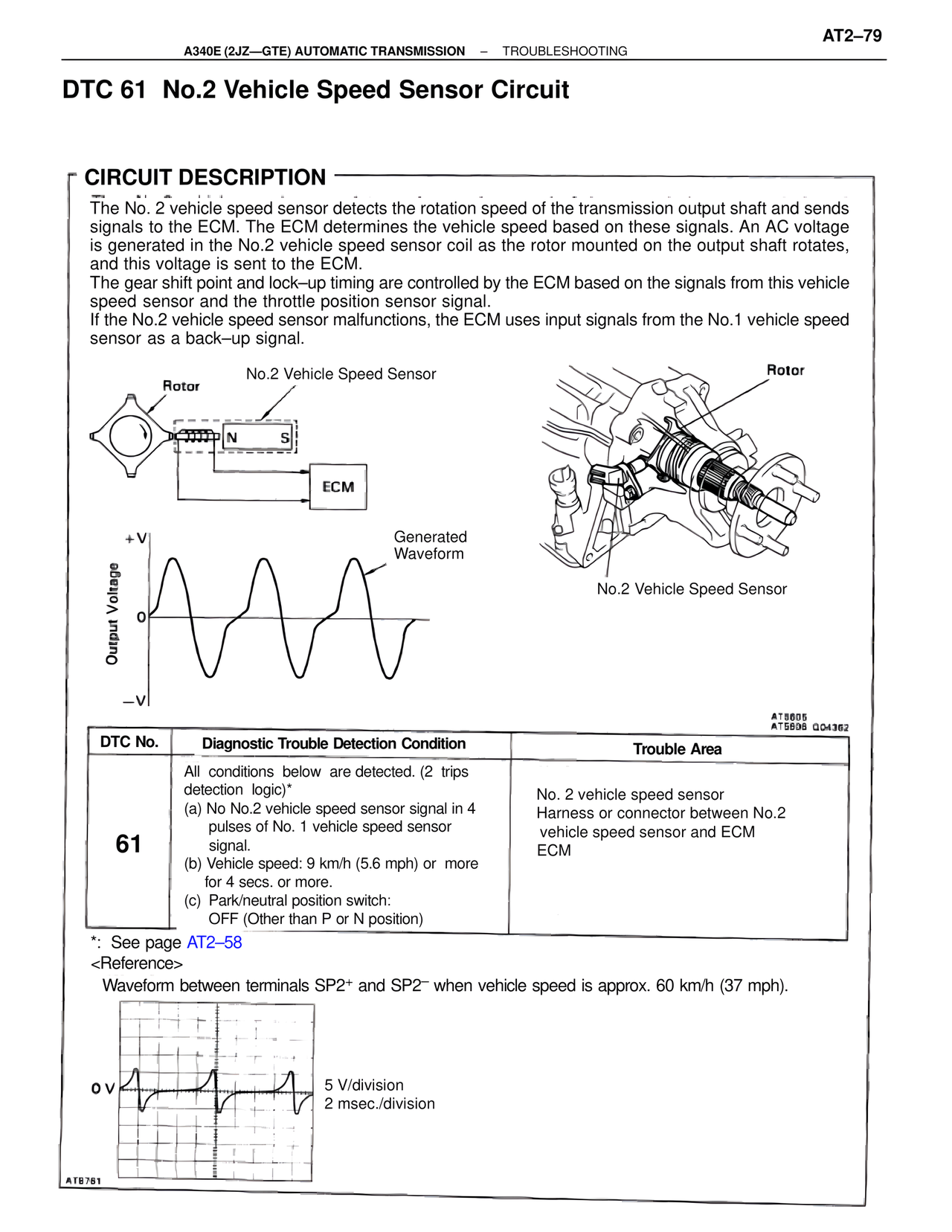
The No. 2 vehicle speed sensor detects the rotation speed of the transmission output shaft and sends
signals to the ECM. The ECM determines the vehicle speed based on these signals. An AC voltage
is generated in the No.2 vehicle speed sensor coil as the rotor mounted on the output shaft rotates,
and this voltage is sent to the ECM.
The gear shift point and lock–up timing are controlled by the ECM based on the signals from this vehicle
speed sensor and the throttle position sensor signal.
If the No.2 vehicle speed sensor malfunctions, the ECM uses input signals from the No.1 vehicle speed
sensor as a back–up signal.
Rotor
No.2 Vehicle Speed Sensor
N S
ECM
+V
Generated
Waveform
Output Voltage
0
–V
Rotor
No.2 Vehicle Speed Sensor
AT5605
AT5598 G04362
DTC No. | Diagnostic Trouble Detection Condition | Trouble Area
61
All conditions below are detected. (2 trips
detection logic)*
(a) No No.2 vehicle speed sensor signal in 4
pulses of No. 1 vehicle speed sensor
signal.
(b) Vehicle speed: 9 km/h (5.6 mph) or more
for 4 secs. or more.
(c) Park/neutral position switch:
OFF (Other than P or N position)
No. 2 vehicle speed sensor
Harness or connector between No.2
vehicle speed sensor and ECM
ECM
*: See page AT2–58
<Reference>
Waveform between terminals SP2+ and SP2– when vehicle speed is approx. 60 km/h (37 mph).
0 V
5 V/division
2 msec./division
AT8781