BR–100
BRAKE SYSTEM – ANTI–LOCK BRAKE SYSTEM (ABS)
DTC 58 TRAC Pump Motor Circuit
CIRCUIT DESCRIPTION
This motor is used to apply hydraulic pressure for the rear wheel brakes during TRAC control.
DTC No. | Diagnostic Trouble Code Detecting Condition | Trouble area
58 | Conditions (1) through (3) continue for 2 sec. or more:
(1) TRAC motor relay: Normal
(2) TRAC motor: OFF
(3) Voltage of ABS & TRAC ECU terminal MTT: 4–8 V | TRAC pump motor
Open in TRAC pump motor circuit
ECU
Fail safe function: If trouble occurs in this circuit, the ECU cuts off current to the TRAC solenoid relay and prohibits TRAC control.
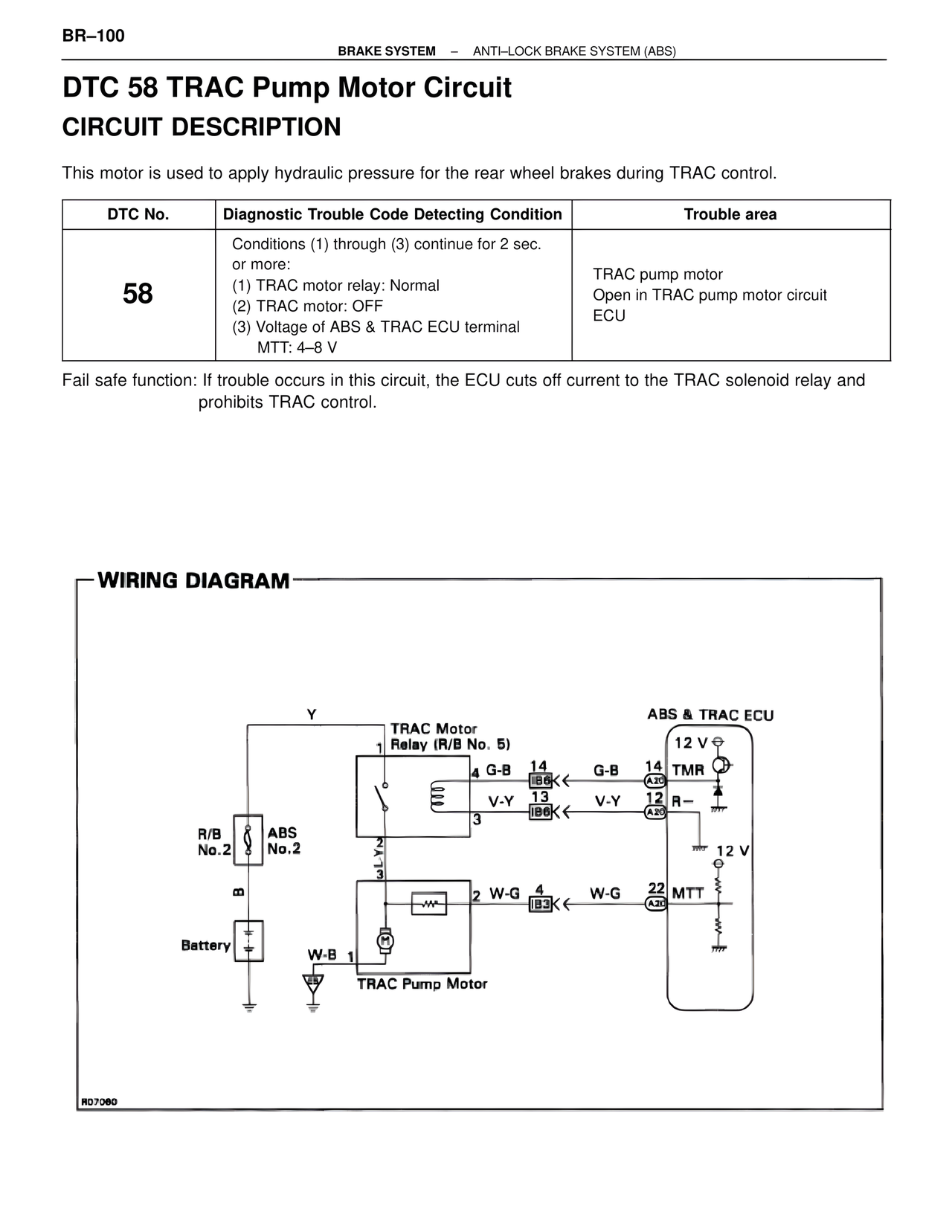
WIRING DIAGRAM
Y
TRAC Motor Relay (R/B No. 5)
1
4 G-B 14 IB6 G-B 14 TMR
V-Y 13 IB6 V-Y 12 R–
3
R/B No.2 ABS No.2
3 LYN
B
2 W-G 4 IB3 W-G 22 MTT
Battery
W-B 1
TRAC Pump Motor
ABS & TRAC ECU
12 V
A20
A20
12 V
A20
R07060