BR–69
BRAKE SYSTEM – ANTI–LOCK BRAKE SYSTEM (ABS)
INSPECTION PROCEDURE (w/ TRAC)
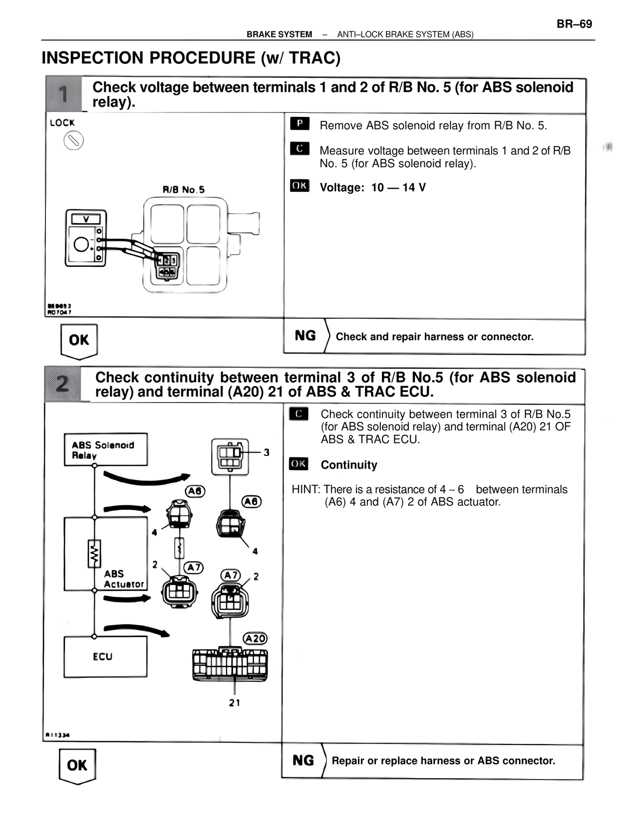
1 Check voltage between terminals 1 and 2 of R/B No. 5 (for ABS solenoid relay).
LOCK
R/B No.5
BE6053
RO7047
P Remove ABS solenoid relay from R/B No. 5.
C Measure voltage between terminals 1 and 2 of R/B No. 5 (for ABS solenoid relay).
OK Voltage: 10 — 14 V
OK
NG Check and repair harness or connector.
2 Check continuity between terminal 3 of R/B No.5 (for ABS solenoid relay) and terminal (A20) 21 of ABS & TRAC ECU.
ABS Solenoid
Relay
3
A6
A6
4
ABS
Actuator
2
A7
A7
2
ECU
A20
21
R11334
C Check continuity between terminal 3 of R/B No.5 (for ABS solenoid relay) and terminal (A20) 21 OF ABS & TRAC ECU.
OK Continuity
HINT: There is a resistance of 4 ~ 6 between terminals (A6) 4 and (A7) 2 of ABS actuator.
OK
NG Repair or replace harness or ABS connector.