BR–77
BRAKE SYSTEM – ANTI–LOCK BRAKE SYSTEM (ABS)
DTC 15 16 TRAC Solenoid Relay Circuit
CIRCUIT DESCRIPTION
This relay circuit supplies power to each traction actuator solenoid.
When the ignition switch is turned ON, the relay goes on.
DTC No. | Diagnostic Trouble Code Detecting Condition | Trouble area
15
Conditions (1) through (3) continue for 0.2 sec. or more:
(1) TRAC solenoid relay terminal (TSR) voltage: Battery positive voltage
(2) All TRAC actuator solenoids: OFF
(3) All TRAC actuator solenoid monitor voltages (in ECU): 0 V
TRAC solenoid relay
Open or short in TRAC solenoid relay circuit
ECU
16
Conditions (1) through (3) continue for 0.2 sec. or more:
(1) TRAC solenoid relay terminal (TSR) voltage: 0 V
(2) All TRAC actuator solenoids: OFF
(3) TRAC actuator solenoid monitor voltage (in ECU): Battery positive voltage
TRAC solenoid relay
B+ short in TRAC solenoid relay circuit
ECU
Fail safe function: If trouble occurs in this relay circuit, the ECU cuts off current to the ABS and TRAC solenoid relays and prohibits ABS and TRAC control.
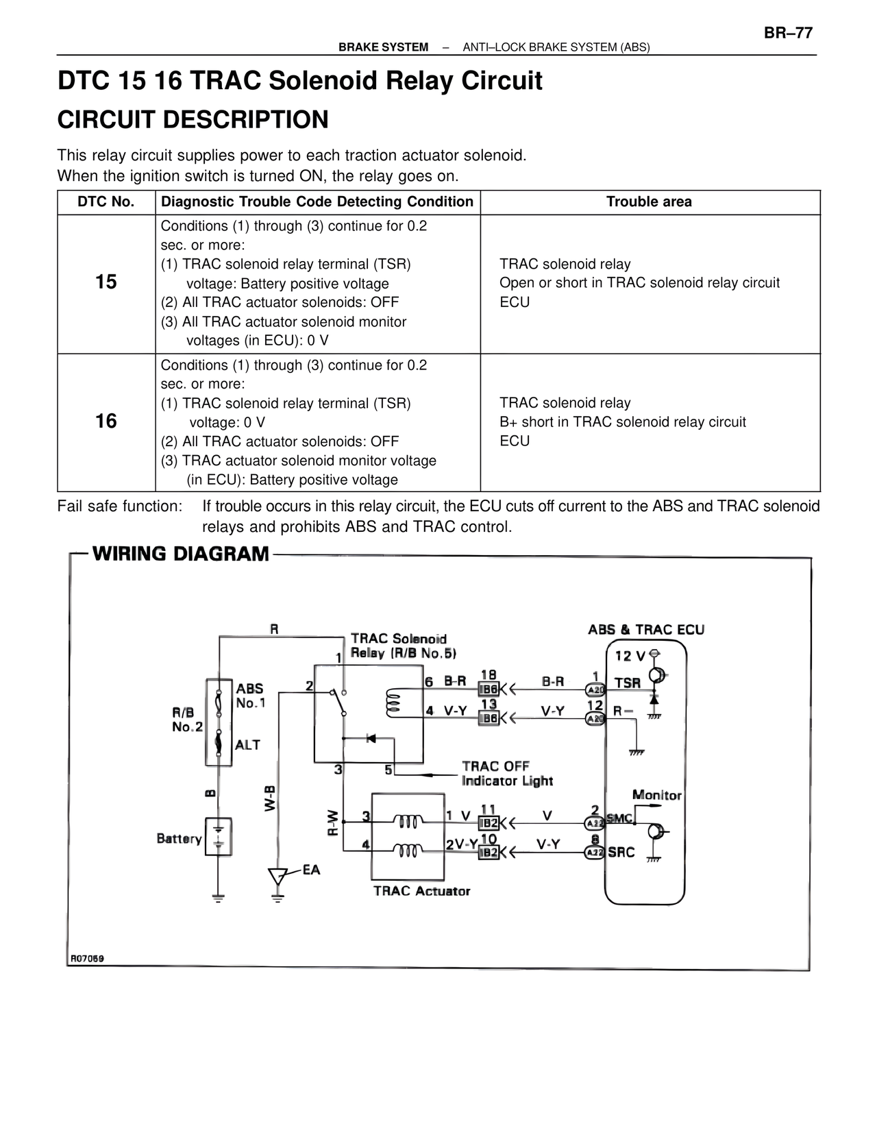
WIRING DIAGRAM
R
TRAC Solenoid Relay (R/B No. 5)
ABS & TRAC ECU
12 V
1
6 B-R 18 B-R 1 TSR
IB6
A20
ABS
2
R/B
No.1
4 V-Y 13 V-Y 12 R–
IB6
A2
No.2
ALT
3 5
TRAC OFF
Indicator Light
Monitor
B
W-B
3 1 V 11 V 2 SMC
R-W
IB2
A13
Battery
4 2V-Y 10 V-Y 8 SRC
IB2
A22
–EA
TRAC Actuator
A07059