BE–131
BODY ELECTRICAL SYSTEM – THEFT DETERRENT AND DOOR LOCK CONTROL SYSTEM
INSPECTION PROCEDURE
HINT: This troubleshooting is based on the premise that engine cranking occurs.
If the engine does not crank, proceed to engine troubleshooting on page EG–381 or 487 (Vol. 1).
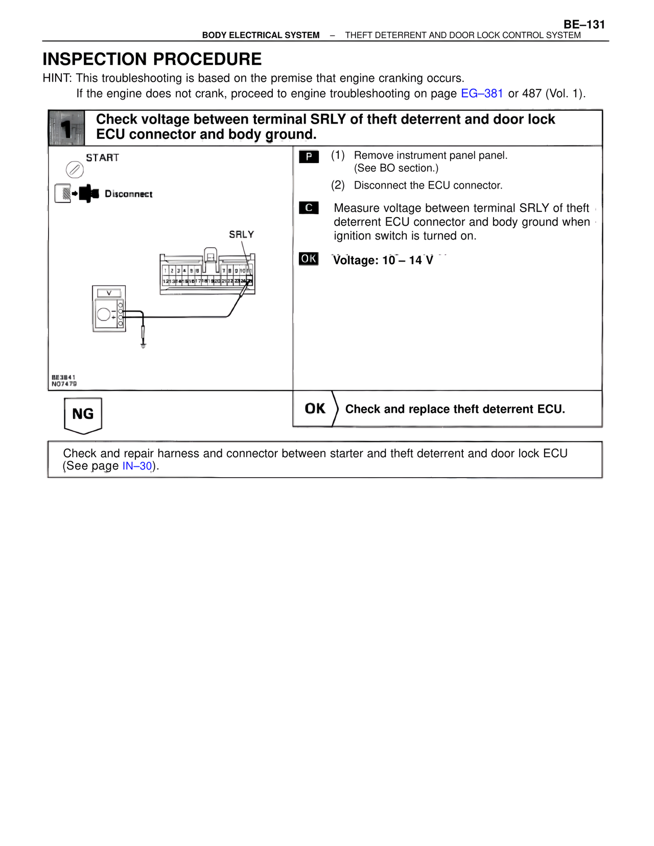
1 Check voltage between terminal SRLY of theft deterrent and door lock ECU connector and body ground.
START
Disconnect
SRLY
P (1) Remove instrument panel panel.
(See BO section.)
(2) Disconnect the ECU connector.
C Measure voltage between terminal SRLY of theft deterrent ECU connector and body ground when ignition switch is turned on.
OK Voltage: 10 – 14 V
BE3B41
NO7479
NG
OK ) Check and replace theft deterrent ECU.
Check and repair harness and connector between starter and theft deterrent and door lock ECU
(See page IN–30).