BE–176
BODY ELECTRICAL SYSTEM – CRUISE CONTROL SYSTEM
INSPECTION PROCEDURE
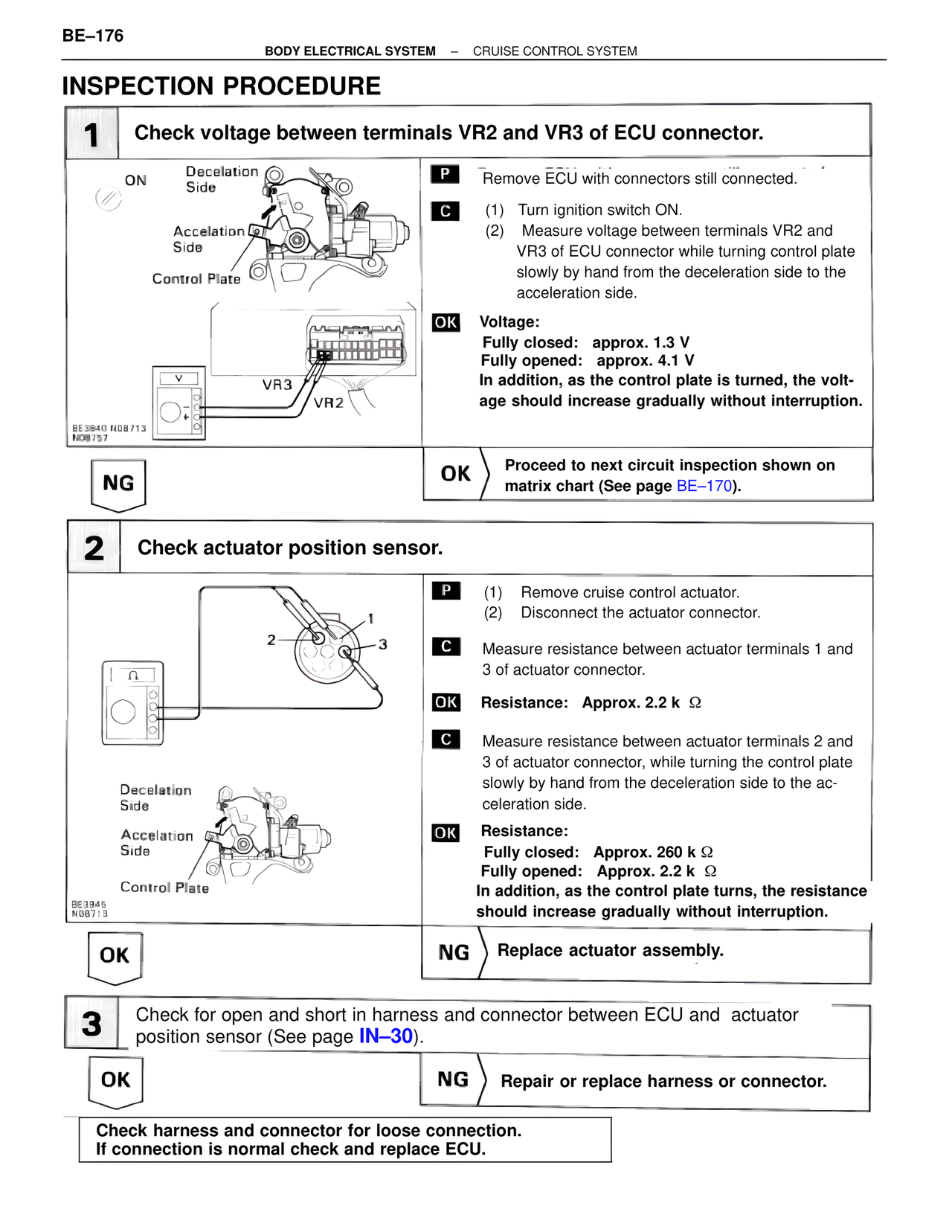
1 Check voltage between terminals VR2 and VR3 of ECU connector.
ON
Decelation Side
Accelation Side
Control Plate
VR3
VR2
BE3840 N08713
N08757
P Remove ECU with connectors still connected.
C (1) Turn ignition switch ON.
(2) Measure voltage between terminals VR2 and VR3 of ECU connector while turning control plate slowly by hand from the deceleration side to the acceleration side.
OK Voltage:
Fully closed: approx. 1.3 V
Fully opened: approx. 4.1 V
In addition, as the control plate is turned, the voltage should increase gradually without interruption.
NG
OK Proceed to next circuit inspection shown on matrix chart (See page BE–170).
2 Check actuator position sensor.
2
1
3
Decelation Side
Accelation Side
Control Plate
BE3945
N08713
P (1) Remove cruise control actuator.
(2) Disconnect the actuator connector.
C Measure resistance between actuator terminals 1 and 3 of actuator connector.
OK Resistance: Approx. 2.2 k Ω
C Measure resistance between actuator terminals 2 and 3 of actuator connector, while turning the control plate slowly by hand from the deceleration side to the acceleration side.
OK Resistance:
Fully closed: Approx. 260 k Ω
Fully opened: Approx. 2.2 k Ω
In addition, as the control plate turns, the resistance should increase gradually without interruption.
OK
NG Replace actuator assembly.
3 Check for open and short in harness and connector between ECU and actuator position sensor (See page IN–30).
OK
NG Repair or replace harness or connector.
Check harness and connector for loose connection.
If connection is normal check and replace ECU.