BE–183
BODY ELECTRICAL SYSTEM – CRUISE CONTROL SYSTEM
INSPECTION PROCEDURE
1 Check operation of stop light.
C Check the stop light comes on when the brake pedal is depressed, and turns off when brake pedal is released.
OK NG Check stop light circuit.
2 Input signal check.
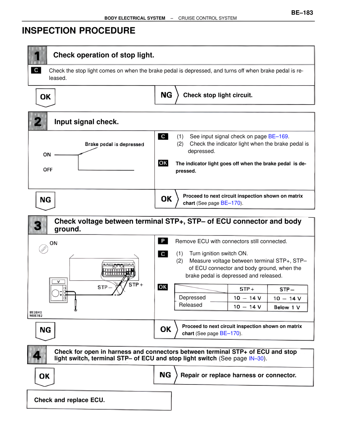
Brake pedal is depressed
ON
OFF
C (1) See input signal check on page BE–169.
(2) Check the indicator light when the brake pedal is depressed.
OK The indicator light goes off when the brake pedal is depressed.
NG OK Proceed to next circuit inspection shown on matrix chart (See page BE–170).
3 Check voltage between terminal STP+, STP– of ECU connector and body ground.
ON
STP– STP+
BE3840
N08782
P Remove ECU with connectors still connected.
C (1) Turn ignition switch ON.
(2) Measure voltage between terminal STP+, STP– of ECU connector and body ground, when the brake pedal is depressed and released.
OK
STP+ STP–
Depressed 10 – 14 V 10 – 14 V
Released 10 – 14 V Below 1 V
NG OK Proceed to next circuit inspection shown on matrix chart (See page BE–170).
4 Check for open in harness and connectors between terminal STP+ of ECU and stop light switch, terminal STP– of ECU and stop light switch (See page IN–30).
OK NG Repair or replace harness or connector.
Check and replace ECU.