BE–192
BODY ELECTRICAL SYSTEM – CRUISE CONTROL SYSTEM
INSPECTION PROCEDURE
1 Check operation of starter.
C Check that the starter operates normally and that the engine starts.
OK NG Proceed to engine troubleshooting (See page
EG–381 or EG–487.)
2 Input signal check.
P (1) See input signal check on page BE–169.
Shifiting into (2) Check the indicator light when shifting into ex–
except D range cept D position.
ON
OK The indicator light goes off when shifting into except D
OFF range.
NG OK Proceed to next circuit inspection shown on matrix
chart (See page BE–170).
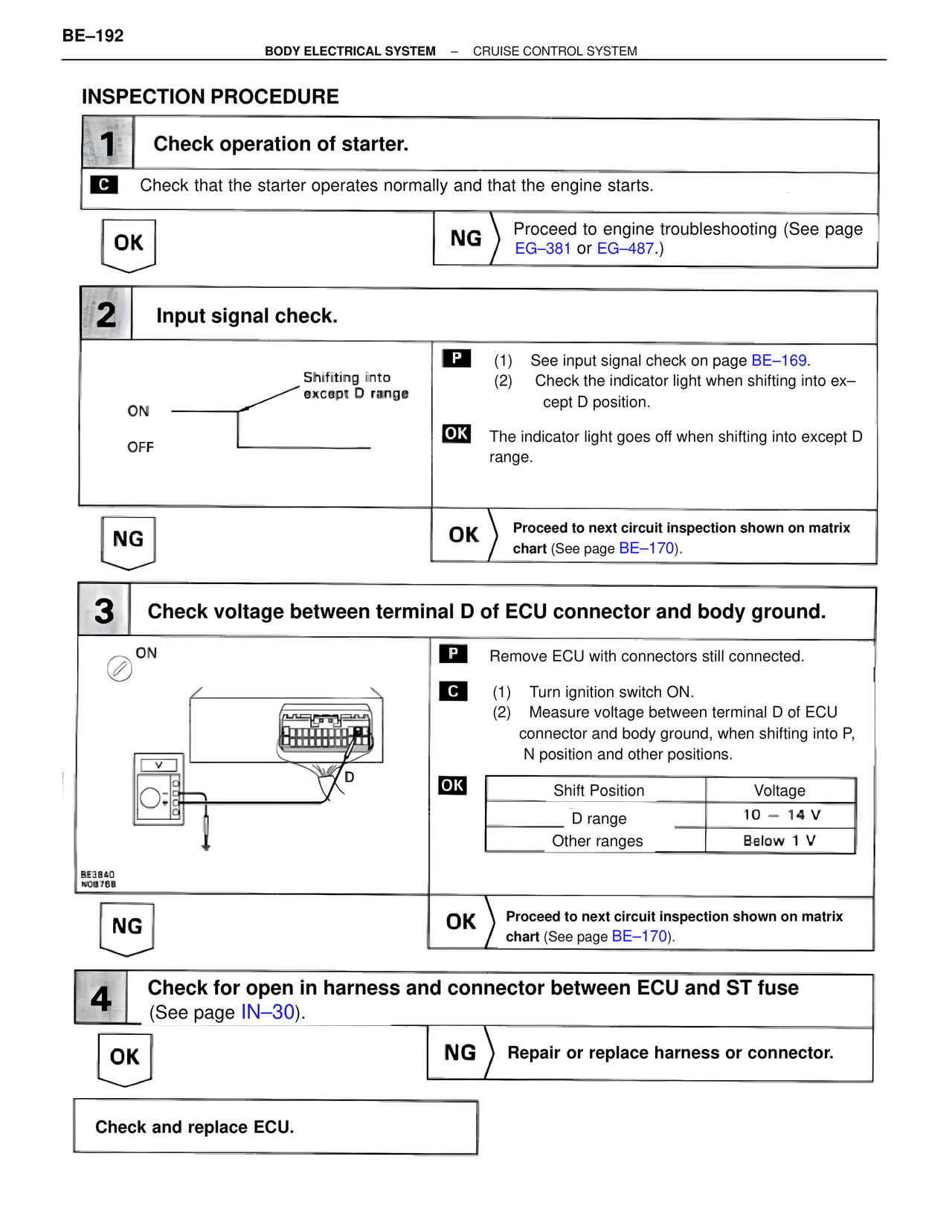
3 Check voltage between terminal D of ECU connector and body ground.
ON P Remove ECU with connectors still connected.
C (1) Turn ignition switch ON.
(2) Measure voltage between terminal D of ECU
connector and body ground, when shifting into P,
N position and other positions.
V OK
Shift Position Voltage
D D range 10 – 14 V
Other ranges Below 1 V
BE3840
NO8768
NG OK Proceed to next circuit inspection shown on matrix
chart (See page BE–170).
4 Check for open in harness and connector between ECU and ST fuse
(See page IN–30).
OK NG Repair or replace harness or connector.
Check and replace ECU.