BE–36
BODY ELECTRICAL SYSTEM – WIPER AND WASHER SYSTEM
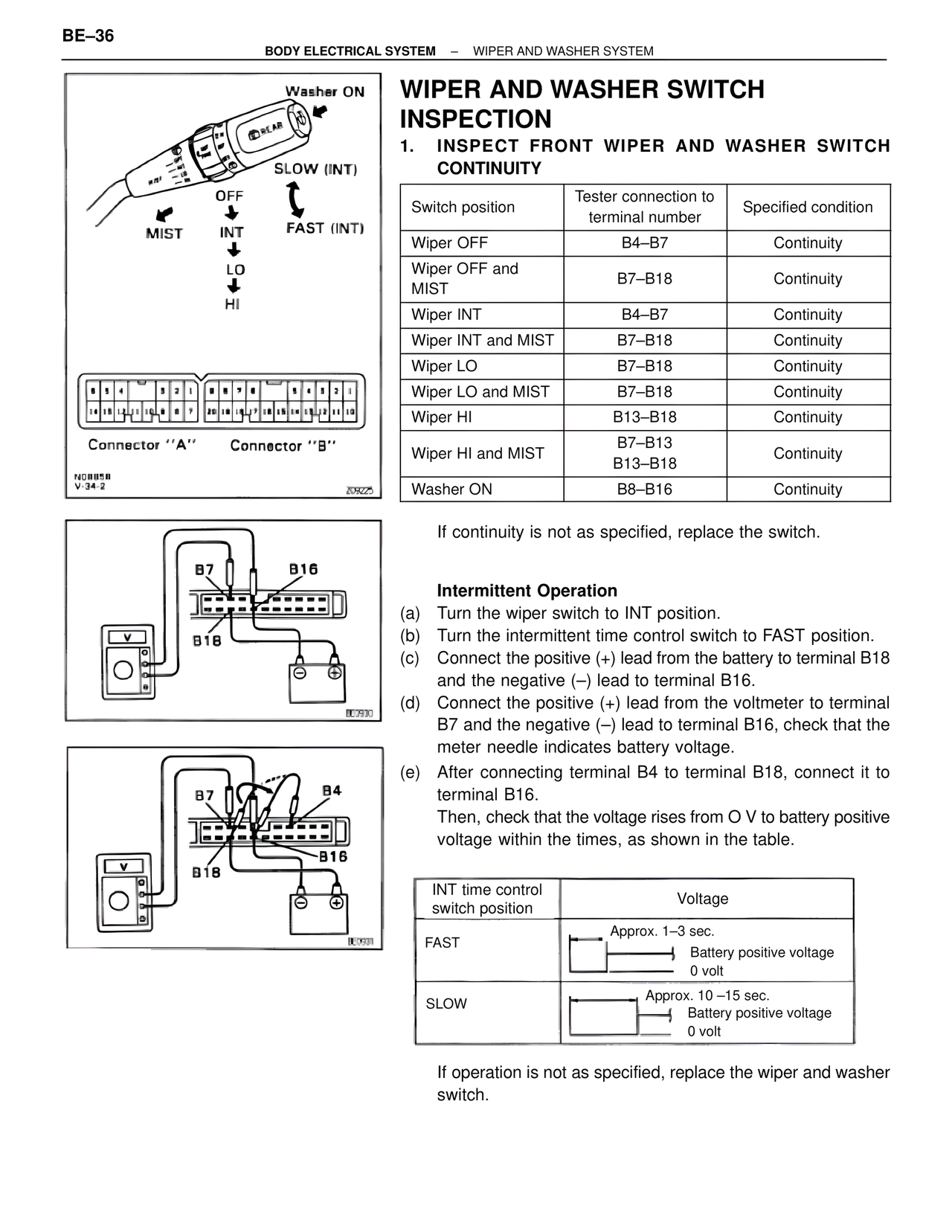
Washer ON
REAR
SLOW (INT)
OFF
FAST (INT)
MIST
INT
LO
HI
Connector "A" Connector "B"
NOBB5B
V-34-2
209225
B7 B16
B18
L07930
B7 B4
B16
B18
L0501
WIPER AND WASHER SWITCH INSPECTION
1. INSPECT FRONT WIPER AND WASHER SWITCH CONTINUITY
Switch position | Tester connection to terminal number | Specified condition
Wiper OFF | B4–B7 | Continuity
Wiper OFF and MIST | B7–B18 | Continuity
Wiper INT | B4–B7 | Continuity
Wiper INT and MIST | B7–B18 | Continuity
Wiper LO | B7–B18 | Continuity
Wiper LO and MIST | B7–B18 | Continuity
Wiper HI | B13–B18 | Continuity
Wiper HI and MIST | B7–B13
B13–B18 | Continuity
Washer ON | B8–B16 | Continuity
If continuity is not as specified, replace the switch.
Intermittent Operation
(a) Turn the wiper switch to INT position.
(b) Turn the intermittent time control switch to FAST position.
(c) Connect the positive (+) lead from the battery to terminal B18
and the negative (–) lead to terminal B16.
(d) Connect the positive (+) lead from the voltmeter to terminal
B7 and the negative (–) lead to terminal B16, check that the
meter needle indicates battery voltage.
(e) After connecting terminal B4 to terminal B18, connect it to
terminal B16.
Then, check that the voltage rises from 0 V to battery positive
voltage within the times, as shown in the table.
INT time control switch position | Voltage
FAST | Approx. 1–3 sec.
Battery positive voltage
0 volt
SLOW | Approx. 10–15 sec.
Battery positive voltage
0 volt
If operation is not as specified, replace the wiper and washer switch.