BE–70
BODY ELECTRICAL SYSTEM – POWER WINDOW CONTROL SYSTEM
BE2054 BE0335
209151
BE2058 BE0335
209152
BE2854 NO8855
209163
BE2658 NO8855
209164
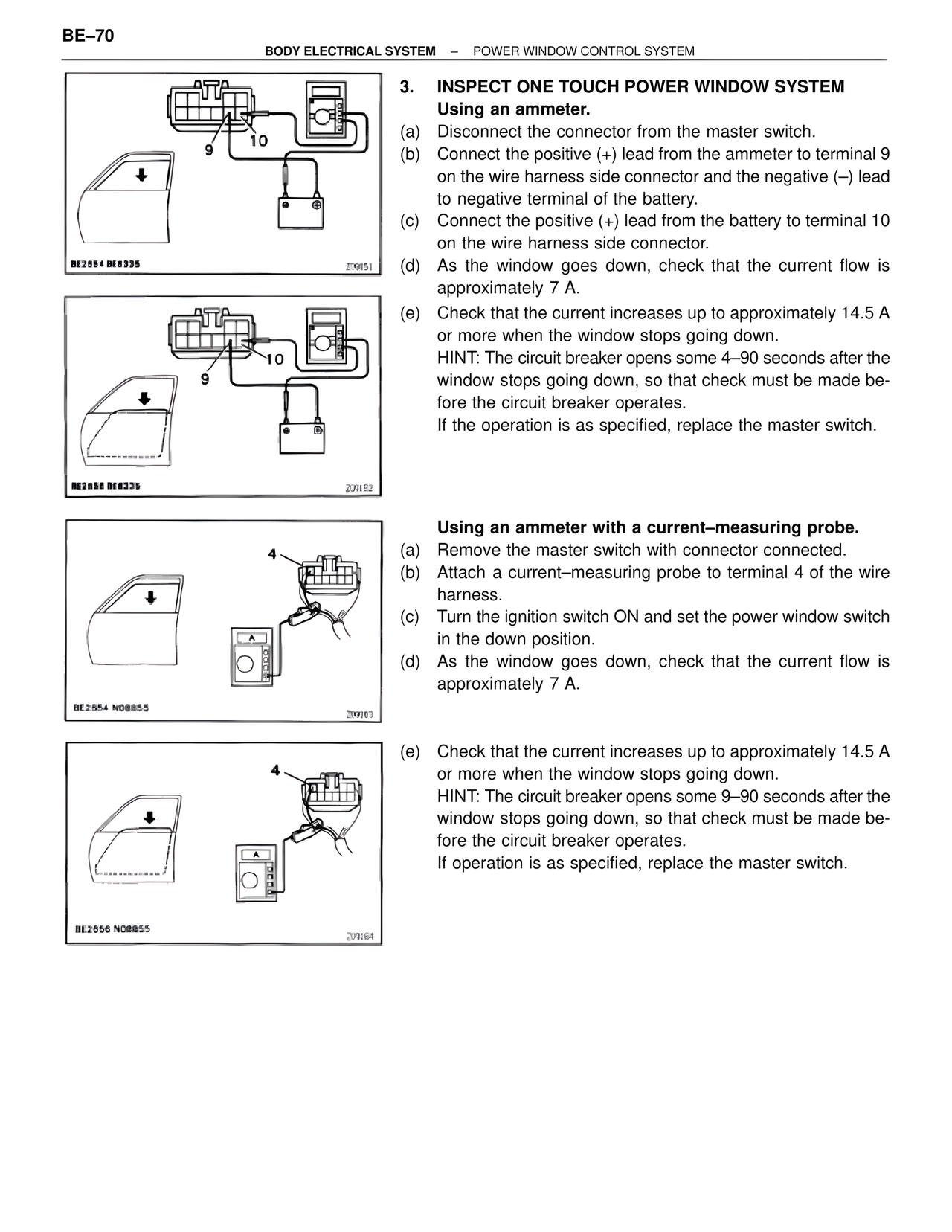
3. INSPECT ONE TOUCH POWER WINDOW SYSTEM
Using an ammeter.
(a) Disconnect the connector from the master switch.
(b) Connect the positive (+) lead from the ammeter to terminal 9
on the wire harness side connector and the negative (–) lead
to negative terminal of the battery.
(c) Connect the positive (+) lead from the battery to terminal 10
on the wire harness side connector.
(d) As the window goes down, check that the current flow is
approximately 7 A.
(e) Check that the current increases up to approximately 14.5 A
or more when the window stops going down.
HINT: The circuit breaker opens some 4–90 seconds after the
window stops going down, so that check must be made be-
fore the circuit breaker operates.
If the operation is as specified, replace the master switch.
Using an ammeter with a current–measuring probe.
(a) Remove the master switch with connector connected.
(b) Attach a current–measuring probe to terminal 4 of the wire
harness.
(c) Turn the ignition switch ON and set the power window switch
in the down position.
(d) As the window goes down, check that the current flow is
approximately 7 A.
(e) Check that the current increases up to approximately 14.5 A
or more when the window stops going down.
HINT: The circuit breaker opens some 9–90 seconds after the
window stops going down, so that check must be made be-
fore the circuit breaker operates.
If operation is as specified, replace the master switch.