BODY DIMENSIONS DI-3
BODY DIMENSION DRAWINGS
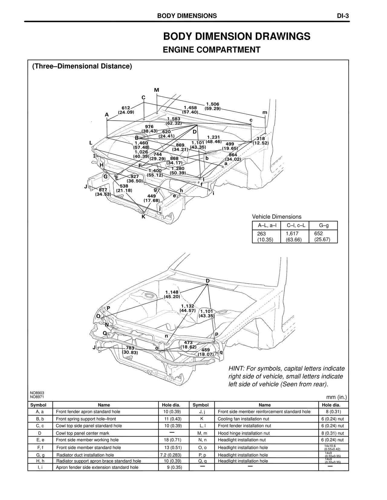
ENGINE COMPARTMENT
(Three–Dimensional Distance)
M
C
1,458 1,506
612 (57.40) (59.29)
(24.09) m
A 1,583
(62.32) c
976
(38.43) 620 D
B (24.41) 1,231
1,460 1,101 (48.46) 499
(57.48) 869 (43.35) (19.65)
L 1,026 (34.21)
(40.39) 744 864
I (29.29) 868 b (34.02)
H (34.17) a
F 1,400 1,280
(55.12) (50.39)
G E 927
(36.50) f
J 538
877 (21.18) g h
(34.53)
449
(17.68)
j
K
Vehicle Dimensions
A–L, a–l C–l, c–L G–g
263 1,617 652
(10.35) (63.66) (25.67)
D
1,148
(45.20)
1,132
(44.57) 1,101
(43.35)
P
O
N n p
Q
J 783
(30.83) o 473
(18.62)
459
(18.07) q
HINT: For symbols, capital letters indicate
right side of vehicle, small letters indicate
left side of vehicle (Seen from rear).
NO8903
NO8971 mm (in.)
Symbol Name Hole dia. Symbol Name Hole dia.
A, a Front fender apron standard hole 10 (0.39) J, j Front side member reinforcement standard hole 8 (0.31)
B, b Front spring support hole–front 11 (0.43) K Cooling fan installation nut 6 (0.24) nut
C, c Cowl top side panel standard hole 10 (0.39) L, l Front fender installation nut 6 (0.24) nut
D Cowl top panel center mark — M, m Hood hinge installation nut 8 (0.31) nut
E, e Front side member working hole 18 (0.71) N, n Headlight installation nut 6 (0.24) nut
F, f Front side member standard hole 13 (0.51) O, o Headlight installation hole 14x10.6
(0.55x0.42)
G, g Radiator duct installation hole 7.2 (0.283) P, p Headlight installation hole 14x9
(0.55x0.35)
H, h Radiator support apron brace standard hole 10 (0.39) Q, q Headlight installation hole 14x9
(0.55x0.35)
I, i Apron fender side extension standard hole 9 (0.35) — — —