EG–67
ENGINE – ENGINE MECHANICAL
P12119
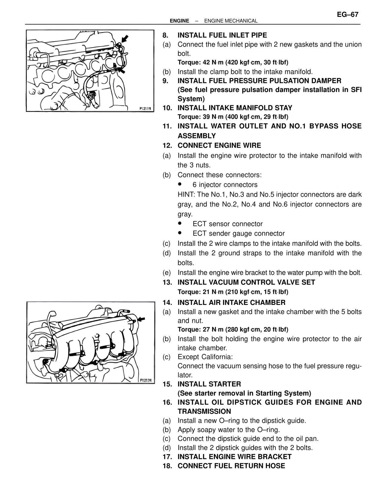
8. INSTALL FUEL INLET PIPE
(a) Connect the fuel inlet pipe with 2 new gaskets and the union bolt.
Torque: 42 N·m (420 kgf·cm, 30 ft·lbf)
(b) Install the clamp bolt to the intake manifold.
9. INSTALL FUEL PRESSURE PULSATION DAMPER
(See fuel pressure pulsation damper installation in SFI System)
10. INSTALL INTAKE MANIFOLD STAY
Torque: 39 N·m (400 kgf·cm, 29 ft·lbf)
11. INSTALL WATER OUTLET AND NO.1 BYPASS HOSE ASSEMBLY
12. CONNECT ENGINE WIRE
(a) Install the engine wire protector to the intake manifold with the 3 nuts.
(b) Connect these connectors:
• 6 injector connectors
HINT: The No.1, No.3 and No.5 injector connectors are dark gray, and the No.2, No.4 and No.6 injector connectors are gray.
• ECT sensor connector
• ECT sender gauge connector
(c) Install the 2 wire clamps to the intake manifold with the bolts.
(d) Install the 2 ground straps to the intake manifold with the bolts.
(e) Install the engine wire bracket to the water pump with the bolt.
13. INSTALL VACUUM CONTROL VALVE SET
Torque: 21 N·m (210 kgf·cm, 15 ft·lbf)
14. INSTALL AIR INTAKE CHAMBER
(a) Install a new gasket and the intake chamber with the 5 bolts and nut.
Torque: 27 N·m (280 kgf·cm, 20 ft·lbf)
(b) Install the bolt holding the engine wire protector to the air intake chamber.
(c) Except California:
Connect the vacuum sensing hose to the fuel pressure regulator.
15. INSTALL STARTER
(See starter removal in Starting System)
16. INSTALL OIL DIPSTICK GUIDES FOR ENGINE AND TRANSMISSION
(a) Install a new O–ring to the dipstick guide.
(b) Apply soapy water to the O–ring.
(c) Connect the dipstick guide end to the oil pan.
(d) Install the 2 dipstick guides with the 2 bolts.
17. INSTALL ENGINE WIRE BRACKET
18. CONNECT FUEL RETURN HOSE
P12124