IG–8
IGNITION SYSTEM – (2JZ–GE)
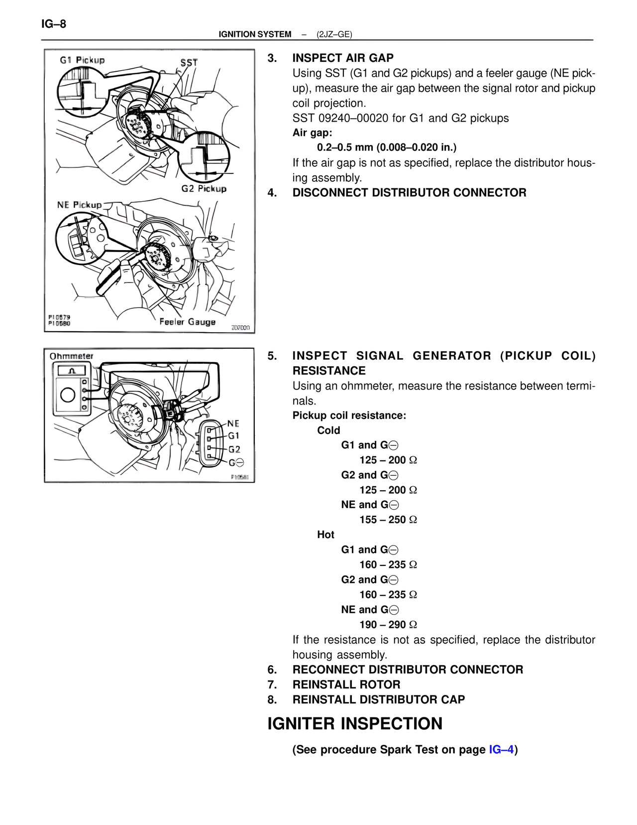
G1 Pickup
SST
G2 Pickup
NE Pickup
Feeler Gauge
P10579
P10580
207020
3. INSPECT AIR GAP
Using SST (G1 and G2 pickups) and a feeler gauge (NE pick-
up), measure the air gap between the signal rotor and pickup
coil projection.
SST 09240–00020 for G1 and G2 pickups
Air gap:
0.2–0.5 mm (0.008–0.020 in.)
If the air gap is not as specified, replace the distributor hous-
ing assembly.
4. DISCONNECT DISTRIBUTOR CONNECTOR
Ohmmeter
NE
G1
G2
G⊖
P10581
5. INSPECT SIGNAL GENERATOR (PICKUP COIL)
RESISTANCE
Using an ohmmeter, measure the resistance between termi-
nals.
Pickup coil resistance:
Cold
G1 and G⊖
125 – 200 Ω
G2 and G⊖
125 – 200 Ω
NE and G⊖
155 – 250 Ω
Hot
G1 and G⊖
160 – 235 Ω
G2 and G⊖
160 – 235 Ω
NE and G⊖
190 – 290 Ω
If the resistance is not as specified, replace the distributor
housing assembly.
6. RECONNECT DISTRIBUTOR CONNECTOR
7. REINSTALL ROTOR
8. REINSTALL DISTRIBUTOR CAP
IGNITER INSPECTION
(See procedure Spark Test on page IG–4)