EG–371
ENGINE – LUBRICATION SYSTEM
INSTALLATION HINT:
Use a new gasket (2JZ–GE) or O–ring (2JZ–GTE).
Torque:
2JZ–GE
49 N·m (500 kgf·cm, 36 ft·lbf)
2JZ–GTE
29 N·m (300 kgf·cm, 22 ft·lbf)
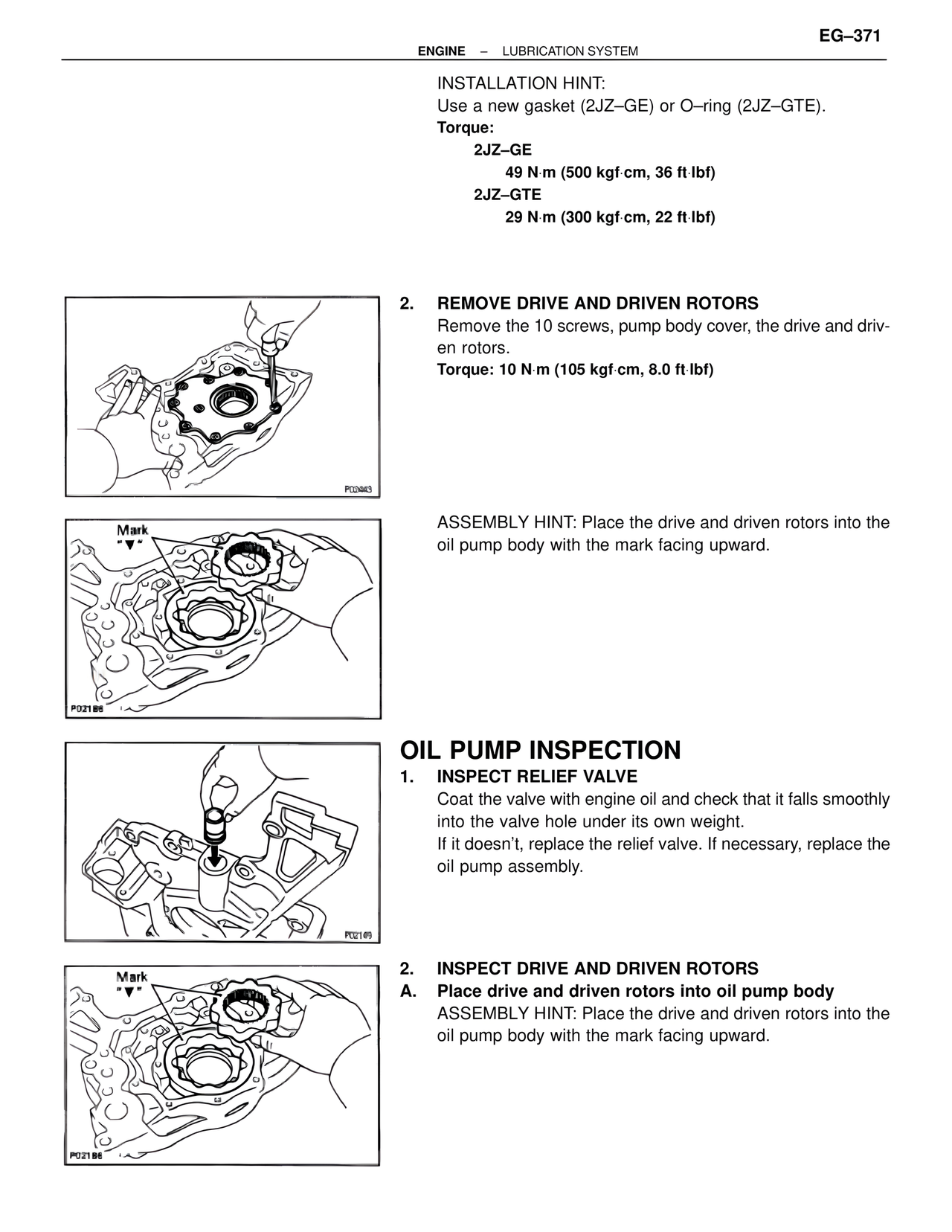
2. REMOVE DRIVE AND DRIVEN ROTORS
Remove the 10 screws, pump body cover, the drive and driven rotors.
Torque: 10 N·m (105 kgf·cm, 8.0 ft·lbf)
Mark
"▼"
ASSEMBLY HINT: Place the drive and driven rotors into the oil pump body with the mark facing upward.
OIL PUMP INSPECTION
1. INSPECT RELIEF VALVE
Coat the valve with engine oil and check that it falls smoothly into the valve hole under its own weight.
If it doesn't, replace the relief valve. If necessary, replace the oil pump assembly.
Mark
"▼"
2. INSPECT DRIVE AND DRIVEN ROTORS
A. Place drive and driven rotors into oil pump body
ASSEMBLY HINT: Place the drive and driven rotors into the oil pump body with the mark facing upward.
P02443
P02186
P02149
P02186