SR–16
STEERING – TILT STEERING COLUMN
Hexagon
Wrench
R07539
Z13448
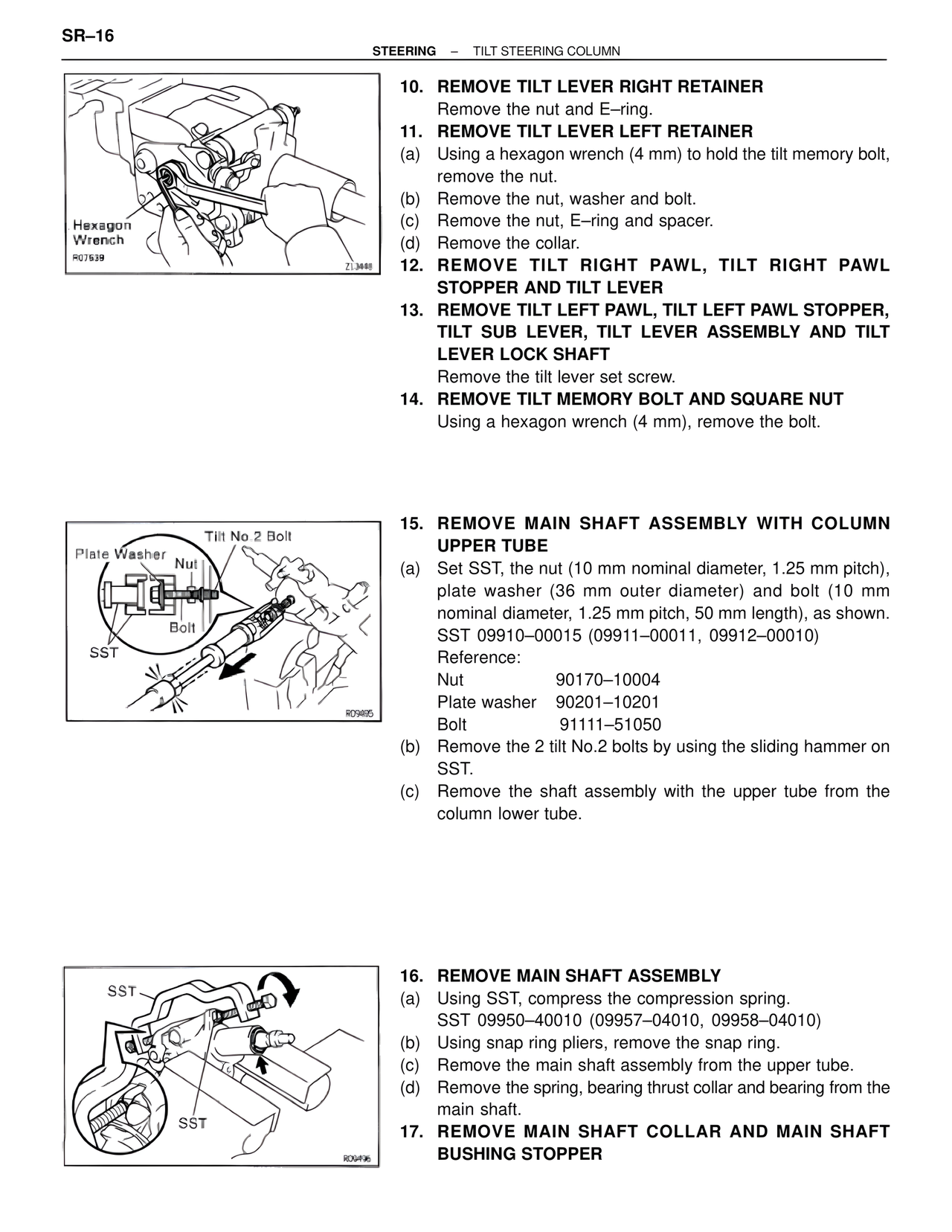
10. REMOVE TILT LEVER RIGHT RETAINER
Remove the nut and E–ring.
11. REMOVE TILT LEVER LEFT RETAINER
(a) Using a hexagon wrench (4 mm) to hold the tilt memory bolt,
remove the nut.
(b) Remove the nut, washer and bolt.
(c) Remove the nut, E–ring and spacer.
(d) Remove the collar.
12. REMOVE TILT RIGHT PAWL, TILT RIGHT PAWL
STOPPER AND TILT LEVER
13. REMOVE TILT LEFT PAWL, TILT LEFT PAWL STOPPER,
TILT SUB LEVER, TILT LEVER ASSEMBLY AND TILT
LEVER LOCK SHAFT
Remove the tilt lever set screw.
14. REMOVE TILT MEMORY BOLT AND SQUARE NUT
Using a hexagon wrench (4 mm), remove the bolt.
Tilt No.2 Bolt
Plate Washer
Nut
Bolt
SST
R09495
15. REMOVE MAIN SHAFT ASSEMBLY WITH COLUMN
UPPER TUBE
(a) Set SST, the nut (10 mm nominal diameter, 1.25 mm pitch),
plate washer (36 mm outer diameter) and bolt (10 mm
nominal diameter, 1.25 mm pitch, 50 mm length), as shown.
SST 09910–00015 (09911–00011, 09912–00010)
Reference:
Nut 90170–10004
Plate washer 90201–10201
Bolt 91111–51050
(b) Remove the 2 tilt No.2 bolts by using the sliding hammer on
SST.
(c) Remove the shaft assembly with the upper tube from the
column lower tube.
SST
SST
R09496
16. REMOVE MAIN SHAFT ASSEMBLY
(a) Using SST, compress the compression spring.
SST 09950–40010 (09957–04010, 09958–04010)
(b) Using snap ring pliers, remove the snap ring.
(c) Remove the main shaft assembly from the upper tube.
(d) Remove the spring, bearing thrust collar and bearing from the
main shaft.
17. REMOVE MAIN SHAFT COLLAR AND MAIN SHAFT
BUSHING STOPPER