SR–18
STEERING – TILT STEERING COLUMN
3. INSTALL MAIN SHAFT ASSEMBLY
(a) Install the bearing, bearing thrust collar and compression spring to the shaft assembly.
(b) Install the shaft assembly into the column upper tube.
NOTICE: Do not bend the universal joint of the main shaft assembly more than 20°.
(c) Using SST, compress the compression spring.
(See page SR–16)
(d) Using snap ring pliers, install a new snap ring.
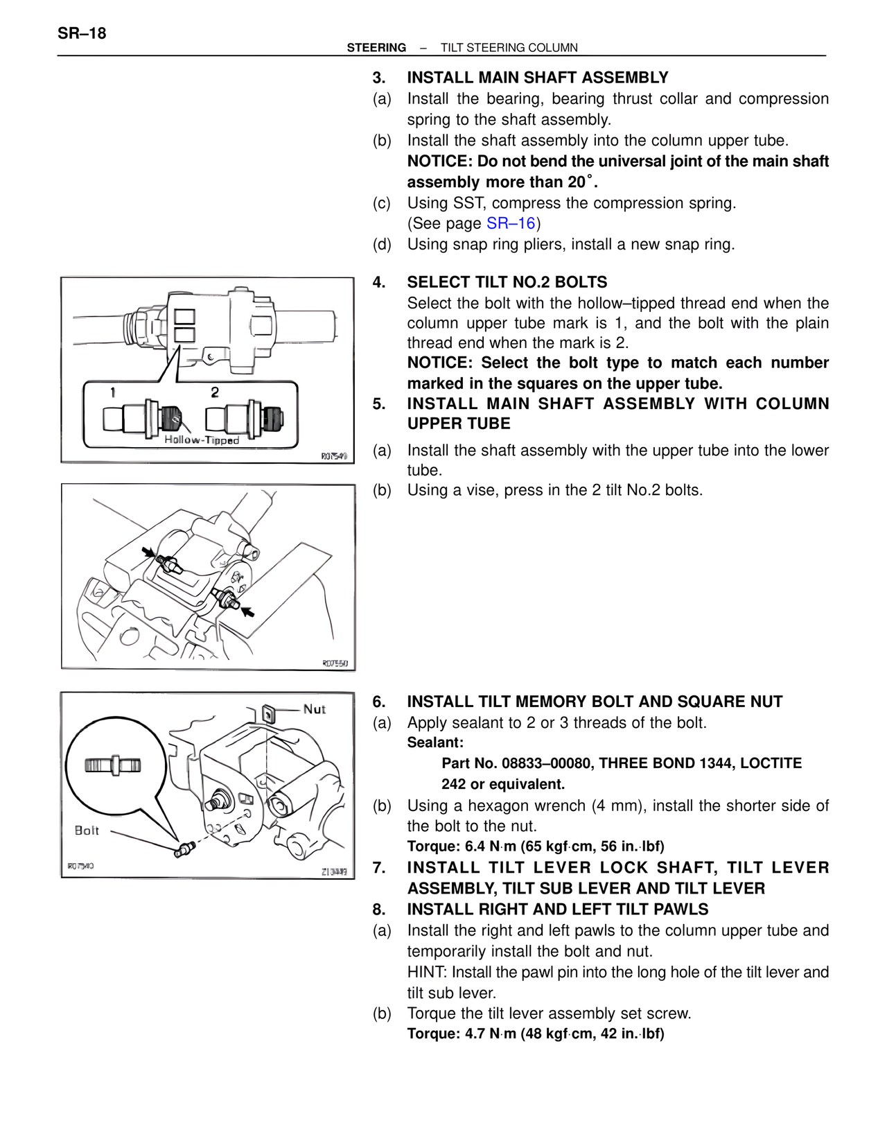
4. SELECT TILT NO.2 BOLTS
Select the bolt with the hollow–tipped thread end when the column upper tube mark is 1, and the bolt with the plain thread end when the mark is 2.
NOTICE: Select the bolt type to match each number marked in the squares on the upper tube.
5. INSTALL MAIN SHAFT ASSEMBLY WITH COLUMN UPPER TUBE
(a) Install the shaft assembly with the upper tube into the lower tube.
(b) Using a vise, press in the 2 tilt No.2 bolts.
1
2
Hollow-Tipped
R07549
R07550
Nut
Bolt
R07540
Z13049
6. INSTALL TILT MEMORY BOLT AND SQUARE NUT
(a) Apply sealant to 2 or 3 threads of the bolt.
Sealant:
Part No. 08833–00080, THREE BOND 1344, LOCTITE 242 or equivalent.
(b) Using a hexagon wrench (4 mm), install the shorter side of the bolt to the nut.
Torque: 6.4 N·m (65 kgf·cm, 56 in.·lbf)
7. INSTALL TILT LEVER LOCK SHAFT, TILT LEVER ASSEMBLY, TILT SUB LEVER AND TILT LEVER
8. INSTALL RIGHT AND LEFT TILT PAWLS
(a) Install the right and left pawls to the column upper tube and temporarily install the bolt and nut.
HINT: Install the pawl pin into the long hole of the tilt lever and tilt sub lever.
(b) Torque the tilt lever assembly set screw.
Torque: 4.7 N·m (48 kgf·cm, 42 in.·lbf)