SR–28
STEERING – POWER STEERING VANE PUMP
POWER STEERING VANE PUMP
INSPECTION AND REPLACEMENT
NOTICE: When using a vise, do not overtighten it.
1. MEASURE OIL CLEARANCE BETWEEN VANE PUMP SHAFT AND BUSHING
Using a micrometer and caliper gauge, measure the oil clearance.
Oil clearance mm (in.)
Standard 0.03–0.05 (0.0012–0.0020)
Maximum 0.07 (0.0028)
2. INSPECT VANE PUMP ROTOR AND VANE PLATES
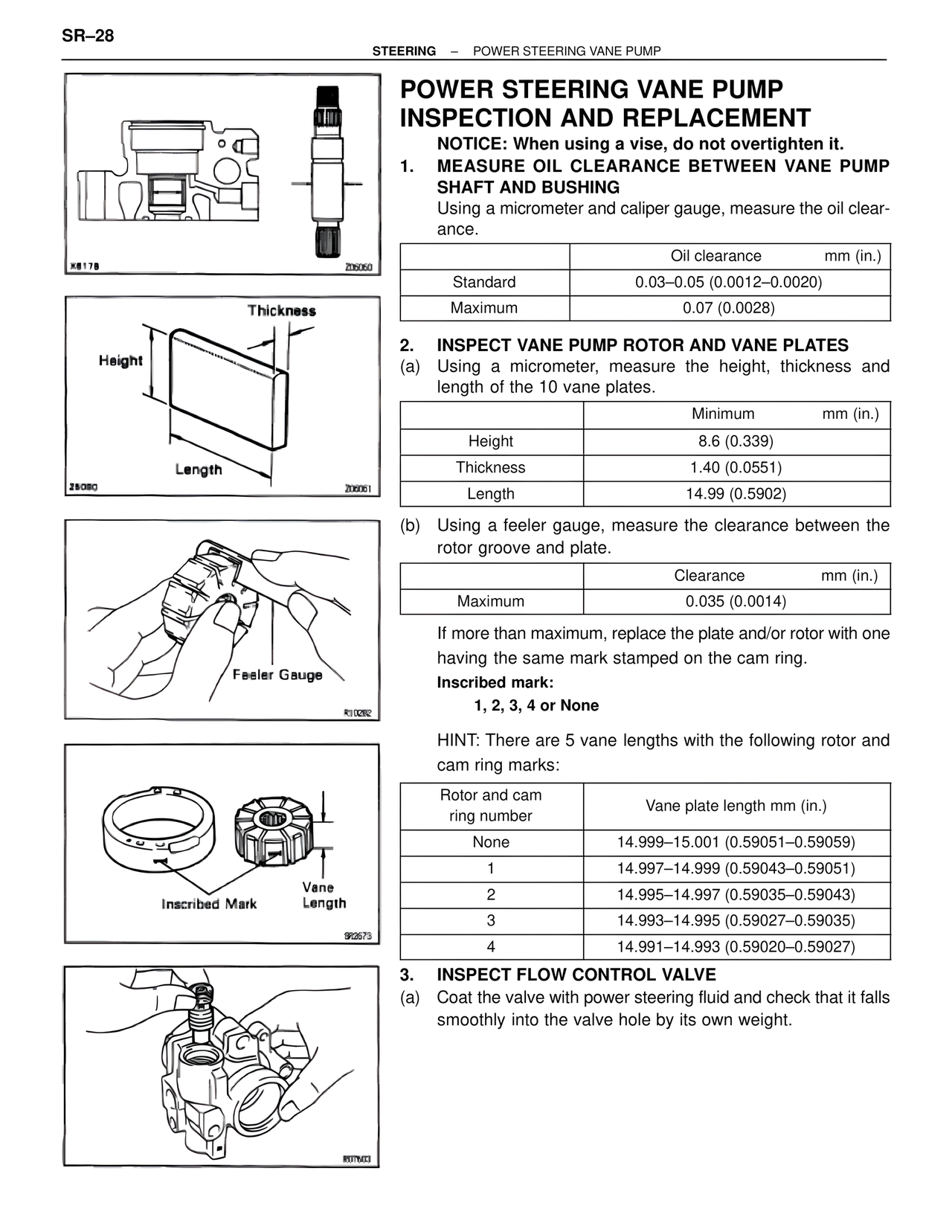
(a) Using a micrometer, measure the height, thickness and length of the 10 vane plates.
Minimum mm (in.)
Height 8.6 (0.339)
Thickness 1.40 (0.0551)
Length 14.99 (0.5902)
(b) Using a feeler gauge, measure the clearance between the rotor groove and plate.
Clearance mm (in.)
Maximum 0.035 (0.0014)
If more than maximum, replace the plate and/or rotor with one having the same mark stamped on the cam ring.
Inscribed mark:
1, 2, 3, 4 or None
HINT: There are 5 vane lengths with the following rotor and cam ring marks:
Rotor and cam ring number Vane plate length mm (in.)
None 14.999–15.001 (0.59051–0.59059)
1 14.997–14.999 (0.59043–0.59051)
2 14.995–14.997 (0.59035–0.59043)
3 14.993–14.995 (0.59027–0.59035)
4 14.991–14.993 (0.59020–0.59027)
3. INSPECT FLOW CONTROL VALVE
(a) Coat the valve with power steering fluid and check that it falls smoothly into the valve hole by its own weight.
Thickness
Height
Length
Feeler Gauge
Inscribed Mark Vane Length
X8178 Z06060
Z8080 Z06061
R10262
SR2673
R07603