UPPER SUSPENSION ARM REMOVAL
Installation is in the reverse order of removal.
INSTALLATION HINT: After installation, check ABS speed
sensor signal and front wheel alignment.
(See page BR–62 and SA–4)
1. REMOVE FRONT WHEEL
Torque: 103 N·m (1,050 kgf·cm, 76 ft·lbf)
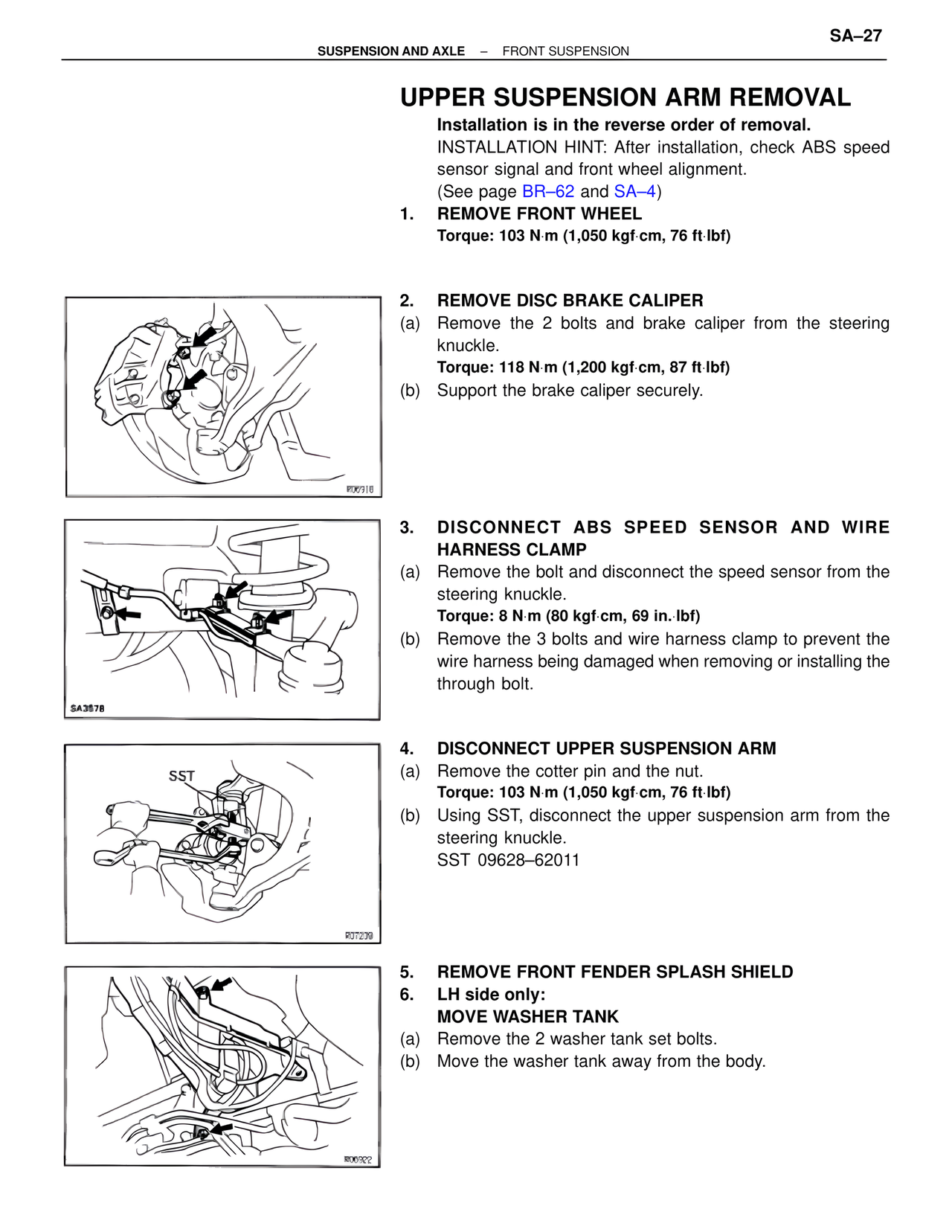
2. REMOVE DISC BRAKE CALIPER
(a) Remove the 2 bolts and brake caliper from the steering
knuckle.
Torque: 118 N·m (1,200 kgf·cm, 87 ft·lbf)
(b) Support the brake caliper securely.
3. DISCONNECT ABS SPEED SENSOR AND WIRE
HARNESS CLAMP
(a) Remove the bolt and disconnect the speed sensor from the
steering knuckle.
Torque: 8 N·m (80 kgf·cm, 69 in.·lbf)
(b) Remove the 3 bolts and wire harness clamp to prevent the
wire harness being damaged when removing or installing the
through bolt.
4. DISCONNECT UPPER SUSPENSION ARM
(a) Remove the cotter pin and the nut.
Torque: 103 N·m (1,050 kgf·cm, 76 ft·lbf)
(b) Using SST, disconnect the upper suspension arm from the
steering knuckle.
SST 09628–62011
5. REMOVE FRONT FENDER SPLASH SHIELD
6. LH side only:
MOVE WASHER TANK
(a) Remove the 2 washer tank set bolts.
(b) Move the washer tank away from the body.