SA–47
SUSPENSION AND AXLE – REAR DRIVE SHAFT
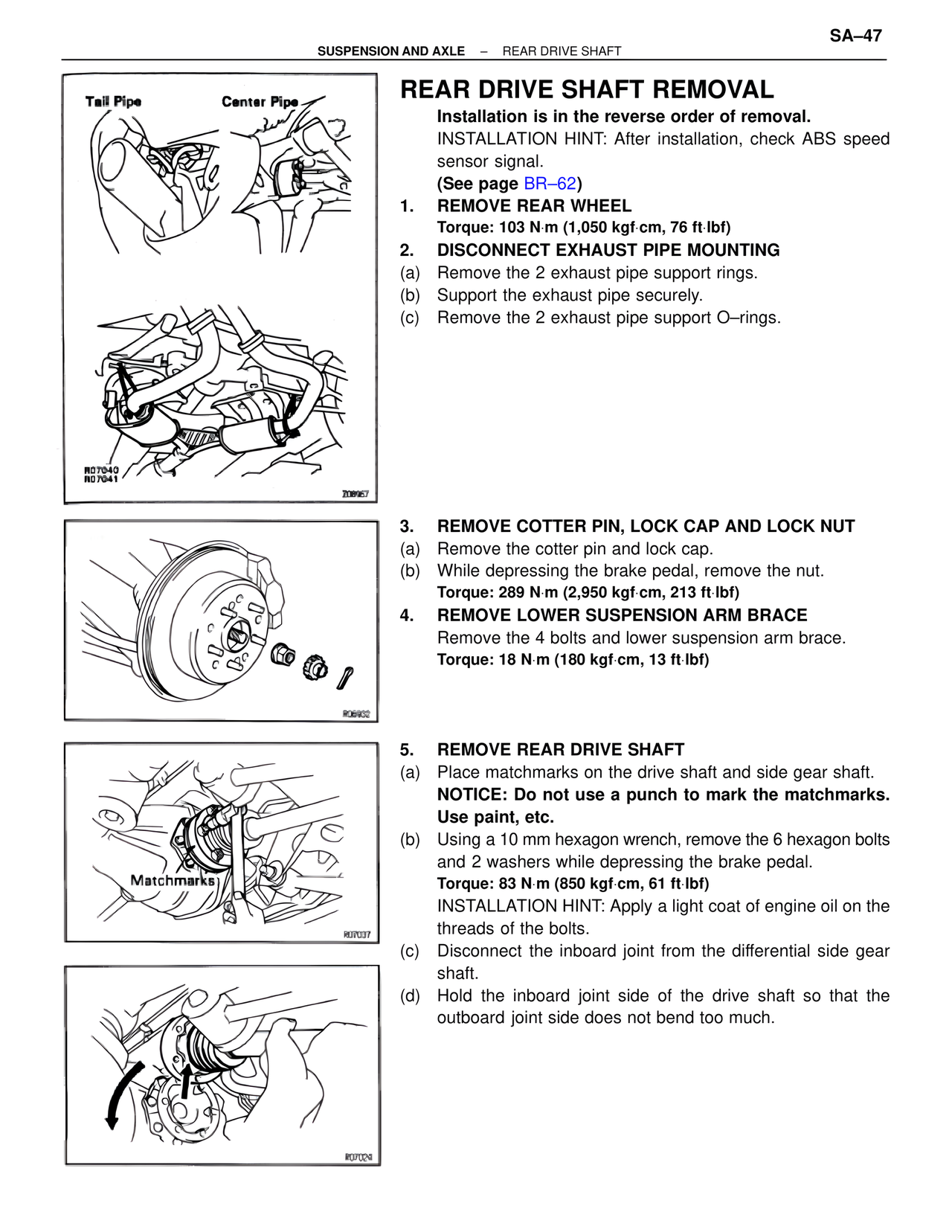
Tail Pipe Center Pipe
R07040
R07041
208967
R06902
Matchmarks
R07037
R07029
REAR DRIVE SHAFT REMOVAL
Installation is in the reverse order of removal.
INSTALLATION HINT: After installation, check ABS speed sensor signal.
(See page BR–62)
1. REMOVE REAR WHEEL
Torque: 103 N·m (1,050 kgf·cm, 76 ft·lbf)
2. DISCONNECT EXHAUST PIPE MOUNTING
(a) Remove the 2 exhaust pipe support rings.
(b) Support the exhaust pipe securely.
(c) Remove the 2 exhaust pipe support O–rings.
3. REMOVE COTTER PIN, LOCK CAP AND LOCK NUT
(a) Remove the cotter pin and lock cap.
(b) While depressing the brake pedal, remove the nut.
Torque: 289 N·m (2,950 kgf·cm, 213 ft·lbf)
4. REMOVE LOWER SUSPENSION ARM BRACE
Remove the 4 bolts and lower suspension arm brace.
Torque: 18 N·m (180 kgf·cm, 13 ft·lbf)
5. REMOVE REAR DRIVE SHAFT
(a) Place matchmarks on the drive shaft and side gear shaft.
NOTICE: Do not use a punch to mark the matchmarks. Use paint, etc.
(b) Using a 10 mm hexagon wrench, remove the 6 hexagon bolts and 2 washers while depressing the brake pedal.
Torque: 83 N·m (850 kgf·cm, 61 ft·lbf)
INSTALLATION HINT: Apply a light coat of engine oil on the threads of the bolts.
(c) Disconnect the inboard joint from the differential side gear shaft.
(d) Hold the inboard joint side of the drive shaft so that the outboard joint side does not bend too much.