ENGINE – SFI SYSTEM (2JZ–GTE)
EG–275
INJECTORS REMOVAL
Installation is in the reverse order of removal.
1. REMOVE ENGINE UNDER COVER
2. REMOVE THROTTLE BODY
(See throttle body removal)
3. REMOVE OIL DIPSTICK AND GUIDE FOR A/T
(a) Remove the bolt.
(b) Pull out the dipstick guide together with the dipstick.
INSTALLATION HINT: Apply soapy water to the O–ring, and
push in the dipstick guide.
(c) Remove the O–ring from the dipstick guide.
INSTALLATION HINT: Use a new O–ring.
4. REMOVE OIL DIPSTICK AND GUIDE FOR ENGINE
(a) Disconnect the fuel return hose from the clamp of the dipstick
guide.
(b) Remove the bolt.
(c) Pull out the dipstick guide together with the dipstick.
INSTALLATION HINT: Apply soapy water to the O–ring, and
push in the dipstick guide.
(d) Remove the O–ring from the dipstick guide.
INSTALLATION HINT: Use a new O–ring.
5. REMOVE AIR INTAKE CHAMBER STAY
Remove the bolt, nut and chamber stay.
Torque: 19 N·m (195 kgf·cm, 14 ft·lbf)
6. DISCONNECT CONTROL CABLE BRACKET FROM AIR
INTAKE CHAMBER
Remove the 2 bolts, and disconnect the cable bracket from
the air intake chamber.
Torque: 19 N·m (195 kgf·cm, 14 ft·lbf)
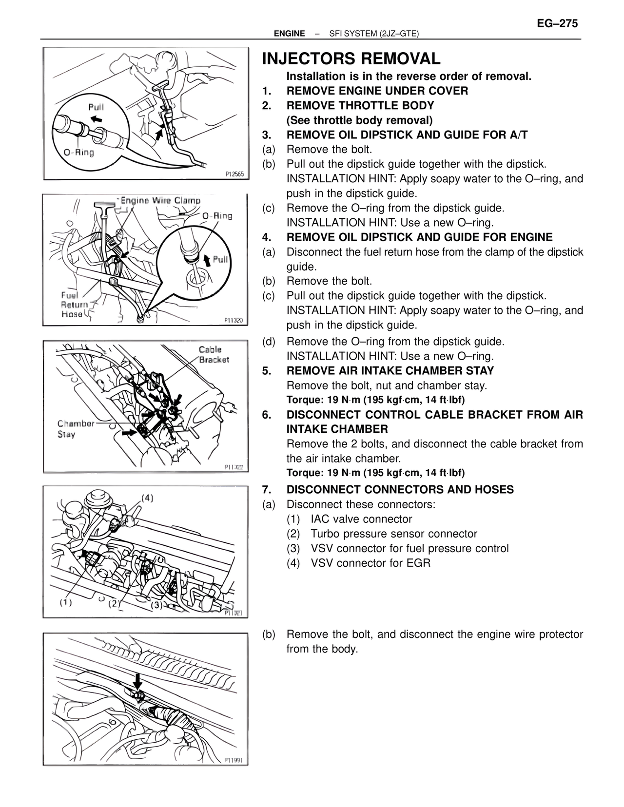
7. DISCONNECT CONNECTORS AND HOSES
(a) Disconnect these connectors:
(1) IAC valve connector
(2) Turbo pressure sensor connector
(3) VSV connector for fuel pressure control
(4) VSV connector for EGR
(b) Remove the bolt, and disconnect the engine wire protector
from the body.
Pull
O–Ring
P12565
Engine Wire Clamp
O–Ring
Pull
Fuel
Return
Hose
P11329
Cable
Bracket
Chamber
Stay
P11322
(4)
(1) (2) (3)
P11321
P11991