ST–6
STARTING SYSTEM – STARTER
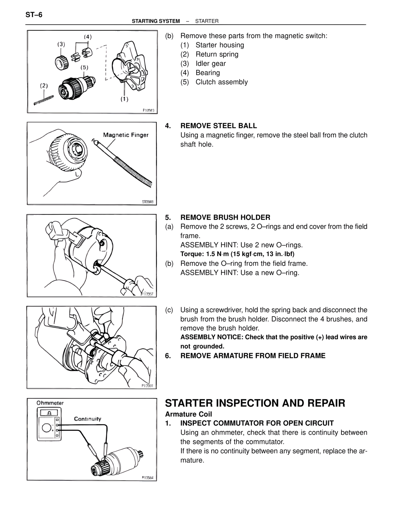
(b) Remove these parts from the magnetic switch:
(1) Starter housing
(2) Return spring
(3) Idler gear
(4) Bearing
(5) Clutch assembly
4. REMOVE STEEL BALL
Using a magnetic finger, remove the steel ball from the clutch shaft hole.
Magnetic Finger
5. REMOVE BRUSH HOLDER
(a) Remove the 2 screws, 2 O–rings and end cover from the field frame.
ASSEMBLY HINT: Use 2 new O–rings.
Torque: 1.5 N·m (15 kgf·cm, 13 in.·lbf)
(b) Remove the O–ring from the field frame.
ASSEMBLY HINT: Use a new O–ring.
(c) Using a screwdriver, hold the spring back and disconnect the brush from the brush holder. Disconnect the 4 brushes, and remove the brush holder.
ASSEMBLY NOTICE: Check that the positive (+) lead wires are not grounded.
6. REMOVE ARMATURE FROM FIELD FRAME
STARTER INSPECTION AND REPAIR
Armature Coil
1. INSPECT COMMUTATOR FOR OPEN CIRCUIT
Using an ohmmeter, check that there is continuity between the segments of the commutator.
If there is no continuity between any segment, replace the armature.
Ohmmeter
Continuity