INSPECTION PROCEDURE
1 Check voltage between terminals VF1, VF2 and E1 of data link connector 1.
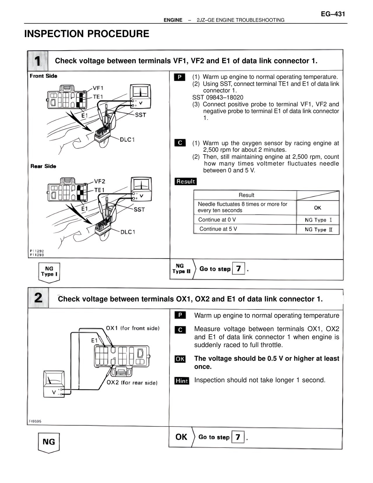
Front Side
VF1
TE1
E1
SST
DLC1
Rear Side
VF2
TE1
E1
SST
DLC1
P11292
P11295
P (1) Warm up engine to normal operating temperature.
(2) Using SST, connect terminal TE1 and E1 of data link connector 1.
SST 09843-18020
(3) Connect positive probe to terminal VF1, VF2 and negative probe to terminal E1 of data link connector 1.
C (1) Warm up the oxygen sensor by racing engine at 2,500 rpm for about 2 minutes.
(2) Then, still maintaining engine at 2,500 rpm, count how many times voltmeter fluctuates needle between 0 and 5 V.
Result
Result
Needle fluctuates 8 times or more for every ten seconds | OK
Continue at 0 V | NG Type I
Continue at 5 V | NG Type II
NG Type I
NG Type II Go to step 7 .
2 Check voltage between terminals OX1, OX2 and E1 of data link connector 1.
OX1 (for front side)
E1
OX2 (for rear side)
F19595
P Warm up engine to normal operating temperature
C Measure voltage between terminals OX1, OX2 and E1 of data link connector 1 when engine is suddenly raced to full throttle.
OK The voltage should be 0.5 V or higher at least once.
Hint Inspection should not take longer 1 second.
NG
OK Go to step 7 .