EG–438
ENGINE – 2JZ–GE ENGINE TROUBLESHOOTING
DTC 31 Volume Air Flow Meter Circuit
CIRCUIT DESCRIPTION
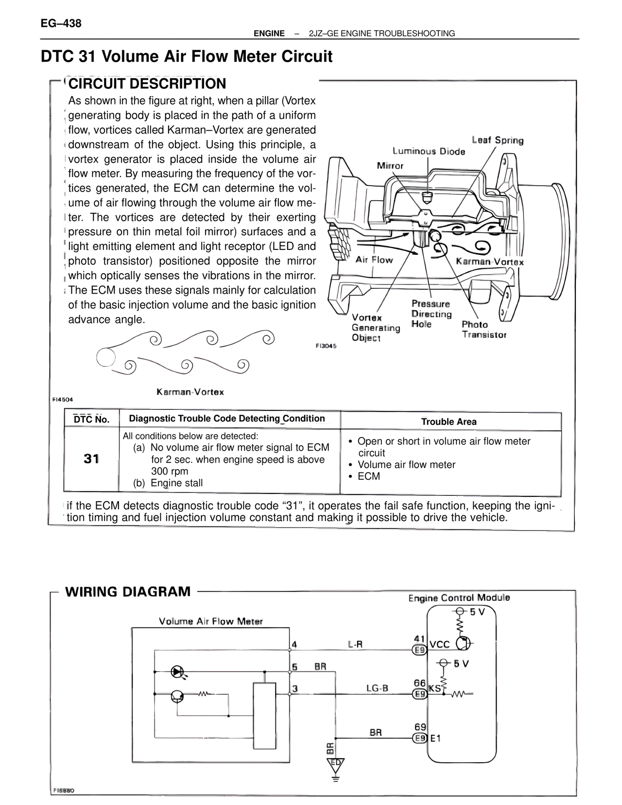
As shown in the figure at right, when a pillar (Vortex generating body is placed in the path of a uniform flow, vortices called Karman–Vortex are generated downstream of the object. Using this principle, a vortex generator is placed inside the volume air flow meter. By measuring the frequency of the vortices generated, the ECM can determine the volume of air flowing through the volume air flow meter. The vortices are detected by their exerting pressure on thin metal foil mirror) surfaces and a light emitting element and light receptor (LED and photo transistor) positioned opposite the mirror which optically senses the vibrations in the mirror. The ECM uses these signals mainly for calculation of the basic injection volume and the basic ignition advance angle.
Karman-Vortex
Leaf Spring
Luminous Diode
Mirror
Air Flow
Karman-Vortex
Vortex Generating Object
Pressure Directing Hole
Photo Transistor
FI3045
FI4504
DTC No. | Diagnostic Trouble Code Detecting Condition | Trouble Area
31
All conditions below are detected:
(a) No volume air flow meter signal to ECM for 2 sec. when engine speed is above 300 rpm
(b) Engine stall
• Open or short in volume air flow meter circuit
• Volume air flow meter
• ECM
if the ECM detects diagnostic trouble code "31", it operates the fail safe function, keeping the ignition timing and fuel injection volume constant and making it possible to drive the vehicle.
WIRING DIAGRAM
Volume Air Flow Meter
4
L-R
41
E9 VCC
5 V
5
BR
3
LG-B
66
E9 KS
5 V
BR
69
E9 E1
BR
ED
Engine Control Module
FI6880