IAC Valve Circuit
CIRCUIT DESCRIPTION
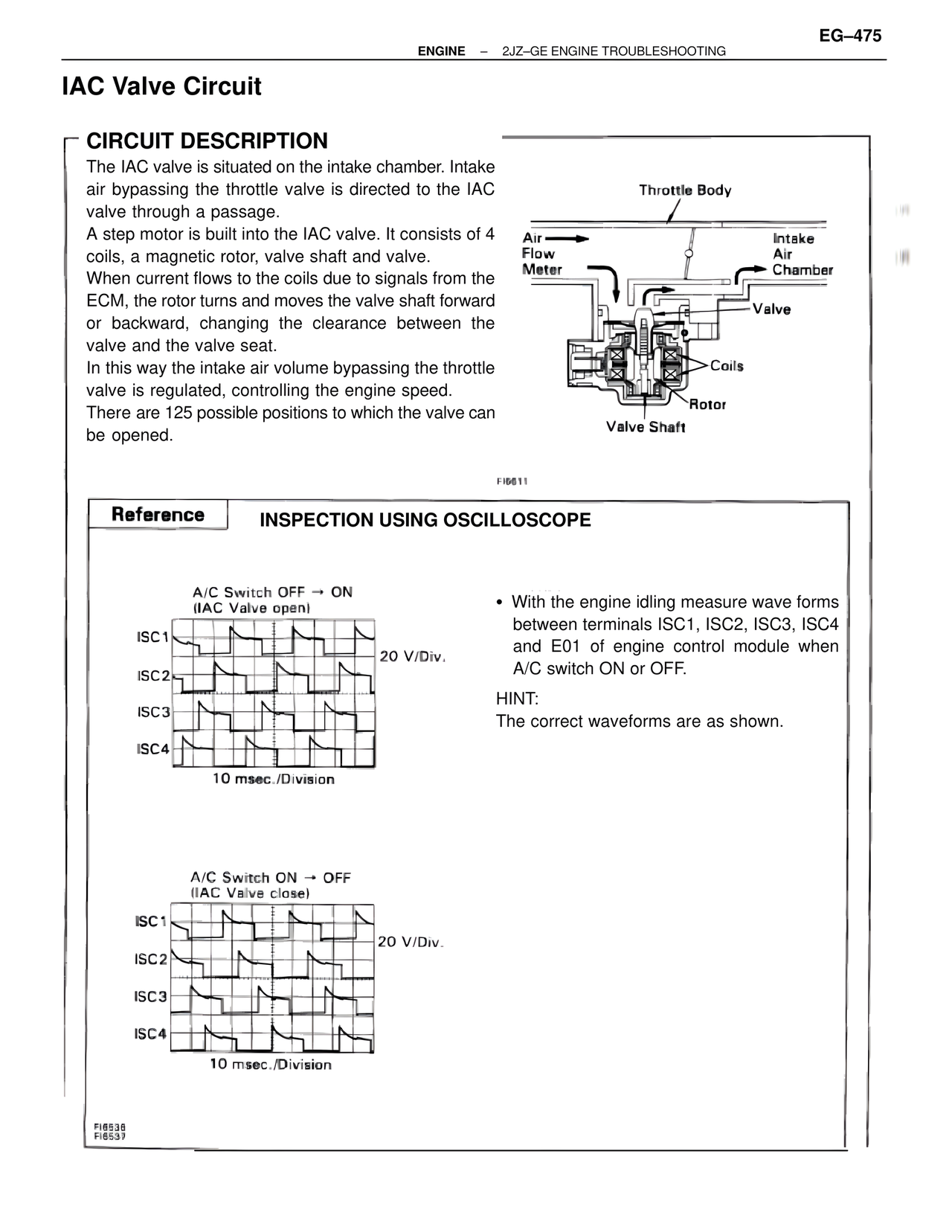
The IAC valve is situated on the intake chamber. Intake
air bypassing the throttle valve is directed to the IAC
valve through a passage.
A step motor is built into the IAC valve. It consists of 4
coils, a magnetic rotor, valve shaft and valve.
When current flows to the coils due to signals from the
ECM, the rotor turns and moves the valve shaft forward
or backward, changing the clearance between the
valve and the valve seat.
In this way the intake air volume bypassing the throttle
valve is regulated, controlling the engine speed.
There are 125 possible positions to which the valve can
be opened.
Throttle Body
Air
Flow
Meter
Intake
Air
Chamber
Valve
Coils
Rotor
Valve Shaft
FI6511
Reference INSPECTION USING OSCILLOSCOPE
A/C Switch OFF → ON
(IAC Valve open)
ISC1
ISC2
20 V/Div.
ISC3
ISC4
10 msec./Division
• With the engine idling measure wave forms
between terminals ISC1, ISC2, ISC3, ISC4
and E01 of engine control module when
A/C switch ON or OFF.
HINT:
The correct waveforms are as shown.
A/C Switch ON → OFF
(IAC Valve close)
ISC1
ISC2
20 V/Div.
ISC3
ISC4
10 msec./Division
FI6538
FI6537